
Page 296 - Applied Petroleum Geomechanics
P. 296
Pore pressure prediction and monitoring 285
(A) (B)
Oil pressure (MPa)
well4 well3 well2 well1 100 110 120 130 140 150 160 170
5500
well1
5750 well2
well3
6000 well4
oil gradient
6250
Depth (m) 6500 Oil gradient = 0.9 g/cc
6750
7000
7250
7500
7750
8000
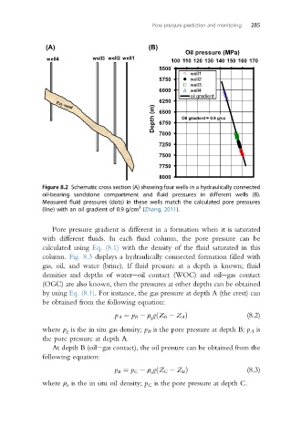
Figure 8.2 Schematic cross section (A) showing four wells in a hydraulically connected
oil-bearing sandstone compartment and fluid pressures in different wells (B).
Measured fluid pressures (dots) in these wells match the calculated pore pressures
3
(line) with an oil gradient of 0.9 g/cm (Zhang, 2011).
Pore pressure gradient is different in a formation when it is saturated
with different fluids. In each fluid column, the pore pressure can be
calculated using Eq. (8.1) with the density of the fluid saturated in this
column. Fig. 8.3 displays a hydraulically connected formation filled with
gas, oil, and water (brine). If fluid pressure at a depth is known; fluid
densities and depths of watereoil contact (WOC) and oilegas contact
(OGC) are also known, then the pressures at other depths can be obtained
by using Eq. (8.1). For instance, the gas pressure at depth A (the crest) can
be obtained from the following equation:
p A ¼ p B r gðZ B Z A Þ (8.2)
g
where r g is the in situ gas density; p B is the pore pressure at depth B; p A is
the pore pressure at depth A.
At depth B (oilegas contact), the oil pressure can be obtained from the
following equation:
o
p B ¼ p C r gðZ C Z B Þ (8.3)
where r o is the in situ oil density; p C is the pore pressure at depth C.