
Page 165 - Applied Process Design For Chemical And Petrochemical Plants Volume II
P. 165
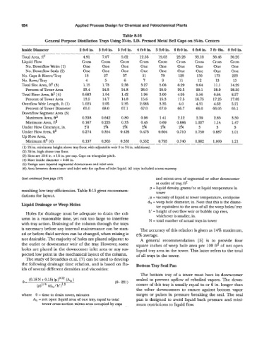
I54                       Applied Process Design for Chemical and Petrochemical Plants

                                                           Table 8-16
                       General Purpose Distillation Trays Using 3%~ I.D. Pressed Metal Bell Caps on 5g-h. Centers

              ~~~
           Inside Diameter             2 ft-6 in.  3 ft-0 in.  3 ft-6 in.  4 ft-0 in.  5 ft-0 in.  6 ft-0 in.  6 ft-6 in.  7 ft- Oh. 8 ft-0 in.
            _--    - --  -                    -__            _ -  __            __ - __ - __
                                                                  -.
            Total Area, ft2             4.91      7.07     9.62    12.56    19.63    28.28   33.18    38.48   50.26
            Liquid Flow                 Cross    Cross    Cross    Cross    Cross    Cross   Cross    Cross   Cross
             No. Downflow Weirs (1)     One       One      One      One      One     One      One     One      One
             No. Downflow Seals (2)     One       One      One      One      One     One      One     One      One
            No. Caps & Risers/Tray       18       27       37        51      79       129     130      173     223
            No. Rows/Tray                 4        5        6        7        9       11       12      13       13
            Total Slot Area, ft2 (3)     1.15     1.73     2.38     3.27     5.08    8.29     9.64    11.1    14.29
             Percent of Tower Area       23.4     24.5     24.8     26.0     25.9    29.3     29.1    28.9    28.50
            Total Riser Area, ft2 (4)   0.683     1.04     1.42     1.96     3.00    4.95     5.36    6.64     8.57
             Percent of Tower Area       13.9     14.7     14.8     13.6     15.3    17.5     16.75   17.25   17.05
            Overflow Weir Length, ft (1)   1.625   2.05    2.35    2.686     3.35     4.0     4.31    4.62     5.21
             Percent of Tower Diameter   65.0     68.0     67.1     67.0     67.0    66.7     66.0    66.05    65.1
            Downflow Segment Area (5)
             Maximum Area, ft2          0.338    0.642     0.80     0.96     1.41    2.12     2.39    2.85     3.50
             Minimum Area, ft2          0.167    0.225     0.33     0.45     0.69    0.886    1.027    1.14    1.47
            Under Flow Clearance, in.    2%       2%       2%       2%       2%       2%       3        3       3
            Under Flow Area, ft2        0.274    0.354    0.426    0.473    0.604    0.710    0.750   0.887    1.01
            Up Flow Area,
                                                                   0.352
                                                                            0.795
                                                          0.335
             Minimum ft2 (6)            0.137    0.365   _-__ - __-  _ -             0.740    0.882   1 .ooo   1.21
                     _______-___--_
                                                                                              -
            (1) 2% in. minimum height above tray floor, with adjustable weir 0 to 3% in. additional.
            (2) 3% in. high above tray floor.
            (3) Slots are 50-M in. x 1% in. per cap. Caps on triangular pitch.
            (4) Riser inside diameter = 2.68 in.
            (5) Design uses tapered segmental downcomer and inlet weir.
            (6) Area between downcomer and inlet weir for upflow of inlet liquid. All trays included access manway.
            (text continued from page 135)                                 and minus area of segmental or other downcomer
                                                                           at outlet of tray, ft2
                                                                        p = liquid density, grams/cc at liquid temperature in
           resulting low tray efficiencies. Table &15 gives recommen-      tower
           dations for layout.                                         . p = viscosity of liquid at tower temperature, centipoise
                                                                       dh  = weep hole diameter, in. Note that this is the diame-
           Liquid Drainage or Weep Holes                                   ter equivalent to the area of all the weep holes/tray
                                                                        h'  = height of overflow weir or bubble cap riser,
             Holes for drainage must be adequate to drain the col-
                                                                           whichever is smaller, in.
           umn in a reasonable time, yet not too large to interfere     N  = total number of actual trays in tower
           with tray action. Draining of the column through the trays
           is necessary before any internal maintenance can be start-   The accuracy of this relation is given as 14% maximum,
           ed or before fluid services can be changed, when mixing is   6% average.
           not desirable. The majority of holes are placed adjacent to   A  general  recommendation  [5]  is  to  provide  four
           the outlet or downcomer weir of  the tray. However, some   square inches of weep hole area per  100 ft2 of  net open
           holes are placed in the downcomer inlet area or any sus-   liquid tray area in the tower. This latter refers to the total
           pected low point in the mechanical layout of the column.   of all trays in the tower.
             The study of Broaddus et al. [7] can be used to develop
           the following drainage time relation, and is based on flu-   Bottom Tray Seal Pan
           ids of several different densities and viscosities:
                                                                    The bottom tray of  a tower must have its downcomer
            e=  (0.18 N + 0.15) (p)'.''   (An )         (8- 221)   sealed to prevent upflow of  reboiled vapors. The down-
                   (p)lI4 (dh / h')'.'                            comer of  this tray is usually equal to or 6 in. longer than
                                                                  the  other  downcomers to  ensure  against bottom vapor
           where  8 = time to drain tower, minutes                surges or pulses in pressure breaking the seal. The sed
                 An = net open liquid area of one tray, equal to total   pan is designed to avoid liquid back pressure and mini-
                     tower cross section minus area occupied by caps   mum restrictions to liquid flow.