
Page 125 - Applied Process Design for Chemical and Petrochemical Plants Volume I
P. 125
112 Applied Process Design for Chemical and Petrochemical Plants
snEEr NO.
LUDWIG CONSULTING ENGINEERS
BY LINE SIZE SHEET Job 210.
Date Charge No.
Line No. Lp - 61 Flow Sheet Drowi>ng No.
Vent through Exchanger for Tower T - 3
LineDescription
Np + Hydrocarbon
Fluid in line Temperature 140 OF
prig
GPM (Calc.) 2060 GPM (des.) 2270 Pressure 11.3 5.3 cu.ft./lb.
Sp. Gr. O.975
*
CFM (des.)
CFM (COIC.)
10,841
12,000
sp. Val.
Lbs./hr.(Colc.)
Lbs./hr.(des.)
Viscosity 0.019
Recommended Velocity
CP
fP ~
Total Eq. Ft.
No.
Unit Eq. Ft.
Item
5
St. 1 ine
I
I
1.56
Total
Total
Estimated line size Iott (existing)
Cross-sect. area, 10" pipe=O.547 sq.ft. Actual Velocity 41 r;n fp
Velocity = 2270/0.547 = 4150 Feet/Min. Unit ~ors per 100 ft. 0.0857 psi
Total head loss
in feet of liquid
Total pressure
drop in psi 1.56
Selected pipe size lo" Material L Weight Schedule 40, Steel
6.31 w = (6.31)(12,OOO) = 3.98 x 10⁵
Colculatians:& $
=
1
f = 0.0158 e= 1/0 CL
(0.000336) (fJ (WJ' - - UUUjjb, (U.m [ IZ,000JL. .
.AP/IOO feet = (10.02)5 (1/11.3)
-
= 0.0857 Psi/lOO equivalent feet of pipe(as pipe,fittings,valves, etc)
,AP Total (friction) = (0.0857/100)(72) = 0.0617 Psi
~
Checked by: Date:
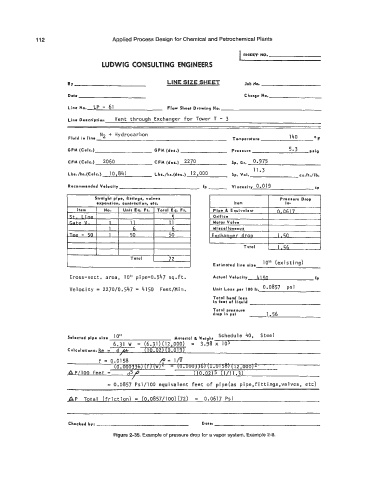
Figure 2-35. Example of pressure drop for a vapor system, Example 2-8.