
Page 221 - Applied Process Design for Chemical and Petrochemical Plants Volume I
P. 221
194 Applied Process Design for Chemical and Petrochemical Plants
reads 100 psia vapor pressure. Then follow the slant lines have similar (not necessarily identical) performance char-
(parallel) to read the scale for NPSH reductions, that is, acteristics. The three main characteristics of capacity,
feet at 9.5 ft. head, and rotative speed are related into a single term
Now the pump selected reads NPSHR on its pump per- designated “specific speed” [ 251. The expression for spe-
formance curve of 12 feet for cold water service. cific speed is the same whether the pump has a single or
double suction impeller.
Now, % of 12 ft = 6 ft The principle significance of specific speed for the
Figure 3-46 reads = 9.5 ft reduction process engineer is to evaluate the expected performance
Corrected value of NPSHR to use = 6 ft, since 9.5 ft is of a second pump in a particular manufacturer’s series
> % the cold water value while basing it on the known performance (or curve) at
the point of optimum efficiency of a first and different
Example 3-11: Alternate to Example 3-10 size pump. In effect the performance of any impeller of a
manufacturer’s homologous series can be estimated from
Assume that a boiler feed water is being pumped at 180 the known performance of any other impeller in the
OF. Read the chart in Figure 3-46 and the water vapor pres- series, at the point of optimum efficiency. Figures 3-48
sure curve, and follow over to read NPSH reduction = and 3-49 represent the standardized conditions of essen-
0.45 feet. A pump selected for the service requires 6 feet tially all pump manufacturers.
cold water service NPSHR:
A typical “operating specific speed” curve is shown
%of6 = 3ft in Figure 3-50 and represents a technique for plotting
Value from chart for 180°F = 0.45 ft reduction the specific speed on the operating performance
Then correct NPSH, to use = 6 ft - 0.45 ft = 5.55 ft curve. Figure 3-50 represents a 6-inch pump operating
required by the pump at 1760 rpm, with maximum efficiency at 1480 GPM
for this service and 132 feet head [25]. The operating specific speed is
zero at no flow and increases to infinity at the maxi-
Specific Speed mum flow of 2270 gpm and zero head. Stable opera-
tions beyond about 1600-1700 gpm cannot be planned
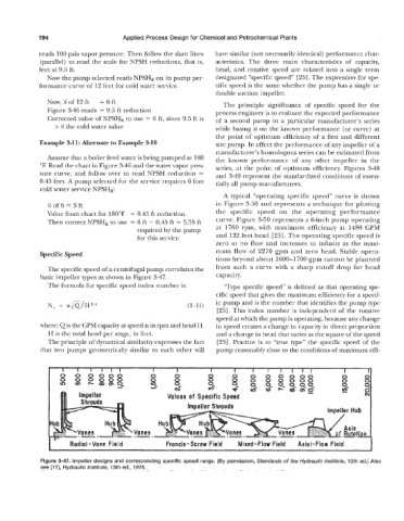
The specific speed of a centrifugal pump correlates the from such a curve with a sharp cutoff drop for head
basic impeller types as shown in Figure 3-47. capacity.
The formula for specific speed index number is: “Type specific speed” is defined as that operating spe-
cific speed that gives the maximum efficiency for a specif-
ic pump and is the number that identifies the pump type
N, = nfi/H3/4 (3-11)
[25]. This index number is independent of the rotative
speed at which the pump is operating, because any change
where: (2 is the GPM capacity at speed n in rpm and head H. in speed creates a change in capacity in direct proportion
H is the total head per stage, in feet. and a change in head that varies as the square of the speed
The principle of dynamical similarity expresses the fact [25]. Practice is to “true type” the specific speed of the
that two pumps geometrically similar to each other will pump reasonably close to the conditions of maximum effi-
I I I I I I I I I I I I I I I I I I I1
*
I cu m- a- F a(- m-g- ..
Impeller Values of Specific Speed
Impeller Shrouds
Radial -Vane Field Francis-Screw Field Mixed-Flow Field Axial-Flow Field
Figure 3-47. Impeller designs and corresponding specific speed range. (By permission, Standards of the Hydraulic Institute, 10th ed.) Also
see [17], Hydraulic Institute, 13th ed., 1975.