
Page 81 - Applied Process Design for Chemical and Petrochemical Plants Volume I
P. 81
Applied Process Design for Chemical and Petrochemical Plants
PIPE DIAMETER IN FEET, D lished values of references [l, 2, 31, and cannot be used
.OS with the values presented in Perry's Handbook [5], as Per-
.04
.03 ry's values for, f, are one-fourth times the values cited in
this chapter. It is essential to use f values with the corre-
sponding formulas offered in the appropriate text.
The Colebrook equation [6, 581 is considered a reli-
able approach to determining the friction factor, f
(Moody factor)
(2 - 18)
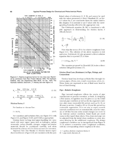
Note that the term E/D is the relative roughness from
Figure 2-11. The solution of the above equation is trial
and error. Colebrook [6] also proposed a direct solution
equation that is reported [7] to have
f = 1.8 loglo (RJ7)-2 (2-1 9)
The equation proposed by Churchill [SI is also a direct
solution with good accuracy ["I.
PIPE DIAMETER IN INCHES, d
RELATIVE ROUGHNESS FACTORS FOR Friction Head Loss (Resistance) in Pipe, Fittings, and
NEW CLEAN PIPES
Connections
Figure 2-11. Relative roughness factors for new clean pipe. Reprint-
ed by permission from Pipe Friction Manual, 1954, The Hydraulic Friction head loss develops as fluids flow through the
Institute. Also see Engineering Data Book, 1st Ed., 1979, The various pipes, elbows, tees, vessel connections, valves, etc.
Hydraulic Institute. Data from L. F. Moody, see note Figure 2-3. These losses are expressed as loss of fluid static head in
feet of fluid flowing.
(2-15) Pipe-Relative Roughness
Pipe internal roughness reflects the results of pipe
22,700qp 50.6Qp 0.482qhSg manufacture or process corrosion, or both. In designing
Re = - (2 - 16)
--=
dv dP dP a flow system, recognition must be given to (a) the initial
internal pipe condition as well as (b) the expected condi-
Friction Factor, f tion after some reasonable life period, such as 10, 15, or
20 years in service. Usually a 10- to 15-year life period is a
For laminar or viscous flow: reasonable expectation. It is not wise to expect smooth
internal conditions over an extended life, even for water,
f = 64/% (2-1 7) air, or oil flow because some actual changes can occur in
the internal surface condition. Some fluids are much
For transition and turbulent flow, use Figure 2-11 with worse in this regard than others. New, clean steel pipe can
Figure 2-3, and Figure 2-12A and 2-12B as appropriate. be adjusted from the initial clean condition to some situ-
Friction factor in long steel pipes handling wet (satu- ation allowing for the additional roughness. The design
rated with water vapor) gases such as hydrogen, carbon roughened condition can be interpolated from Figure 2-
monoxide, carbon dioxide, nitrogen, oxygen and similar 11 to achieve a somewhat more roughened condition,
materials should be considered carefully, and often with the corresponding relative roughness E/D value.
increased by a factor of 1.2 to 2.0 to account for corrosion.
Important Note: The Moody [l] friction factors repro- E = epsilon, absolute roughness factor, ft
duced in this text (Figure 2-3) are consistent with the pub- D = pipe inside diameter, ft