
Page 112 - 05. Subyek Teknik Mesin - Automobile Mechanical and Electrical Systems Automotive Technology Vehicle Maintenance and Repair (Vehicle Maintenance Repr Nv2) by Tom Denton
P. 112
2
96 Automobile mechanical and electrical systems
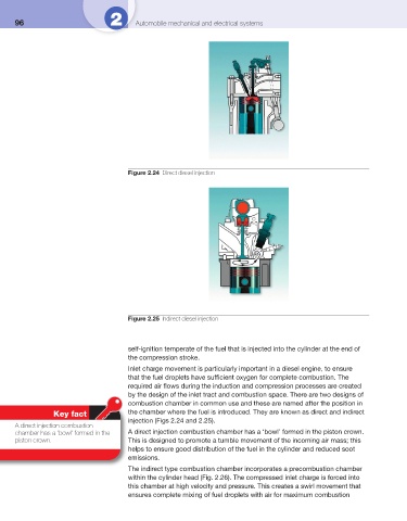
Figure 2.24 Direct diesel injection
Figure 2.25 Indirect diesel injection
self-ignition temperate of the fuel that is injected into the cylinder at the end of
the compression stroke.
Inlet charge movement is particularly important in a diesel engine, to ensure
that the fuel droplets have suffi cient oxygen for complete combustion. The
required air fl ows during the induction and compression processes are created
by the design of the inlet tract and combustion space. There are two designs of
combustion chamber in common use and these are named after the position in
Key fact the chamber where the fuel is introduced. They are known as direct and indirect
injection ( Figs 2.24 and 2.25 ).
A direct injection combustion
chamber has a ‘bowl’ formed in the A direct injection combustion chamber has a ‘bowl’ formed in the piston crown.
piston crown. This is designed to promote a tumble movement of the incoming air mass; this
helps to ensure good distribution of the fuel in the cylinder and reduced soot
emissions.
The indirect type combustion chamber incorporates a precombustion chamber
within the cylinder head ( Fig. 2.26 ). The compressed inlet charge is forced into
this chamber at high velocity and pressure. This creates a swirl movement that
ensures complete mixing of fuel droplets with air for maximum combustion