
Page 118 - Automotive Engineering Powertrain Chassis System and Vehicle Body
P. 118
CH AP TER 5 .1 Transmissions and driveline
1st gear
2nd gear
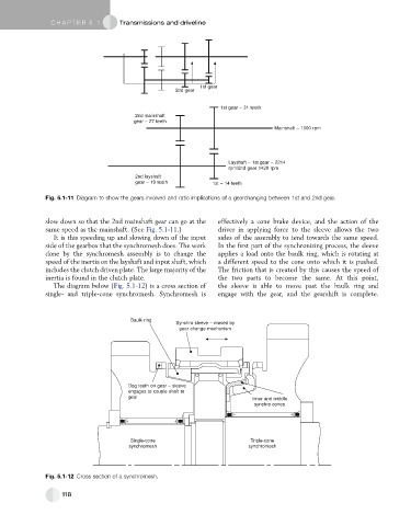
1st gear – 31 teeth
2nd mainshaft
gear – 27 teeth
Mainshaft – 1000 rpm
Layshaft – 1st gear – 2214
rpm/2nd gear 1420 rpm
2nd layshaft
gear – 19 teeth 1st – 14 teeth
Fig. 5.1-11 Diagram to show the gears involved and ratio implications of a gearchanging between 1st and 2nd gear.
slow down so that the 2nd mainshaft gear can go at the effectively a cone brake device, and the action of the
same speed as the mainshaft. (See Fig. 5.1-11.) driver in applying force to the sleeve allows the two
It is this speeding up and slowing down of the input sides of the assembly to tend towards the same speed.
side of the gearbox that the synchromesh does. The work In the first part of the synchronizing process, the sleeve
done by the synchromesh assembly is to change the applies a load onto the baulk ring, which is rotating at
speed of the inertia on the layshaft and input shaft, which a different speed to the cone onto which it is pushed.
includes the clutch driven plate. The large majority of the The friction that is created by this causes the speed of
inertia is found in the clutch plate. the two parts to become the same. At this point,
The diagram below (Fig. 5.1-12) is a cross section of the sleeve is able to move past the baulk ring and
single- and triple-cone synchromesh. Synchromesh is engage with the gear, and the gearshift is complete.
Baulk ring
Synchro sleeve – moved by
gear change mechanism
Dog teeth on gear – sleeve
engages to couple shaft to
gear
Inner and middle
synchro cones
Single-cone Triple-cone
synchromesh synchromesh
Fig. 5.1-12 Cross section of a synchromesh.
118