
Page 25 - Battery Reference Book
P. 25
1/10 Introduction to battery technology
prevented. On the other hand, if the external e.m.f. is while the lead peroxide is re-formed according to the
slightly greater than that of the cell, the reverse process equation:
occurs; the copper electrode dissolves while metallic
zinc is deposited on the zinc electrode. PbS04 + 2Hz0 + PbOz + HzS04 + 2e- + 2HS
A further example of a primary cell is the well
known LeclanchC carbon-zinc cell. This consists of Overall, the charge cell reaction is:
a zinc rod anode dipping into ammonium chloride 2PbSO4 + 2Hz0 -+ Pb + PbOz + 2HzSO4
paste outside a linen bag inside which is a carbon
rod cathode surrounded by solid powdered manganese It is clear from the above equations that in the
dioxide which acts as a chemical depolarizer. discharging process water is formed, so that the rel-
The equation expressing the cell reaction is as fol- ative density of the acid solution drops steadily. Con-
lows: versely, in the charging process the acid concentration
increases. Indeed, the state of charge of an accumu-
2Mn02 + 2NH4Cl+ Zn -+ 2MnOOH + Zn(NH3)2C1z
lator is estimated from the density of the electrolyte,
The e.m.f. is about 1.4V. Owing to the fairly slow which varies from about 1.15 when completely dis-
action of the solid depolarizer, the cell is only suitable charged to 1.21 when fully charged. Throughout all
for supplying small or intermittent currents. these processes the e.m.f. remains approximately con-
The two cells described above are primary (non- stant at 2.1 V and is therefore useless as a sign of the
rechargeable) cells, that is, cells in which the nega- degree of charge in the battery.
tive electrode is dissolved away irreversibly as time The electromotive force mentioned above is that of
goes on. Such cells, therefore, would require replace- the charged accumulator at open circuit. During the
ment of the negative electrode, the electrolyte and the passage of current, polarization effects occur, as dis-
depolarizer before they could be re-used. Secondary cussed earlier, which cause variations of the voltage
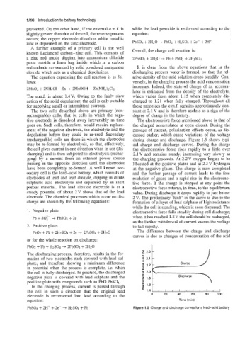
(rechargeable) cells are those in which the electrodes during charge and discharge. Figure 1.5 shows typi-
may be re-formed by electrolysis, so that, effectively, cal charge and discharge curves. During the charge
the cell gives current in one direction when in use (dis- the electromotive force rises rapidly to a little over
charging) and is then subjected to electrolysis (rechar- 2.1 V and remains steady, increasing very slowly as
ging) by a current from an external power source the charging proceeds. At 2.2V oxygen begins to be
passing in the opposite direction until the electrodes liberated at the positive plates and at 2.3V hydrogen
have been completely re-formed. A well known sec- at the negative plates. The charge is now completed
ondary cell is the lead-acid battery, which consists of and the further passage of current leads to the free
electrodes of lead and lead dioxide, dipping in dilute evolution of gases and a rapid rise in the electromo-
sulphuric acid electrolyte and separated by an inert tive force. If the charge is stopped at any point the
porous material. The lead dioxide electrode is at a electromotive force returns, in time, to the equilibrium
steady potential of about 2V above that of the lead value. During discharge it drops rapidly to just below
electrode. The chemical processes which occur on dis- 2V. The preliminary ‘kink’ in the curve is due to the
charge are shown by the following equations: formation of a layer of lead sulphate of high resistance
while the cell is standing, which is soon dispersed. The
1. Negative plate: electromotive force falls steadily during cell discharge;
Pb + SO:- -+ PbS04 + 2e when it has reached 1.8 V the cell should be recharged,
as the further withdrawal of current causes the voltage
2. Positive plate: to fall rapidly.
PbOz + Pb + 2HzSO4 + 2e -+ 2PbSO4 + 2HzO The difference between the charge and discharge
curves is due to changes of concentration of the acid
or for the whole reaction on discharge:
PbOz -5 Pb + + 2PbSO4 + 2HzO
I
+
The discharging process, therefore, results in the for- - 2.6 -
mation of two electrodes each covered with lead sul- $ 2.4 -
phate, and therefore showing a minimum difference
in potential when the process is complete, i.e. when
the cell is fully discharged. In practice, the discharged .-
negative plate is covered with lead sulphate and the E 1.8 - Discharge
positive plate with compounds such as PbO.PbS04. P
In the charging process, current is passed through 5 1.6 -
the cell in such a direction that the original lead ii 1.4-
electrode is reconverted into lead according to the 0 20 40 60 80 100
equation: Time (rnin)
PbSO4 + 2H+ + 2e- -+ HzS04 + Pb Figure Id Charge and discharge curves for a lead-acid battery