
Page 392 - Battery Reference Book
P. 392
Nickel-zinc secondary batteries 33/7
1.8
613
1.7
- 1.6
>
7.5
I
0
r 1.4
P
__
-
8 1.3
1.2
1 . 'I
1.0 I I I I I I I
14 50 100 150 200 250 300
Capacity (Ah)
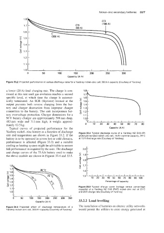
Figure 33.2 Projected performance at various discharge rates for a Yardney nickel-zinc cell, 300A h capacity (Courtesy of Yardney)
a lower (20A) final charging rate. The charge is con- 1.8r
tinued at this rale until gas evolution reaches a second
specific level, a.t which time the charge is automat-
ically terminated. An SCR (thyristor) located at the
output prevents both reverse charging from the bat-
tery and charger destruction from improper charger
connection to the battery. The unit incorporates bat-
tery overvoltage protection. Charger dimensions for a
96 V battery charger are approximately 508 mm deep,
483 mrn wide and 71 1 mm high; it weighs approxi-
mately 63.5 kg. 0 10 20 30 40 50 60 70 80
Typical curves of projected performance for the Capacity (Ah)
Yardney nickel-zinc battery as a function of discharge Figure 33.4 Typical discharge curve of a Yardney NZ EV3-XPI
rate and temperature are shown in Figure 33.2. If the prototype bonded nickel-zinc cell, 75A h nominal capacity, 25°C
battery is to be operated in severe hot or cold climates, at 15A discharge rate (Courtesy of Yardney)
performance is affected (Figure 33.3) and a suitable
cooling or heating system might be advisable to restore
full performance as required by the user. The discharge
and charge curves of the 75 Ah battery used to make
the above module are shown in Figures 33.4 and 33.5.
1.5 :::FYL-I
30
40
70
60
20
50
10
Percentage of capacity 80 90 100
Figure 33.5 Typical charge curve (voltage versus percentage
capacity) of a Yardney NZ EV6 (FIAT) nickel-zinc cell at 25°C
and 25A charge rate (Courtesy of Yardney)
0 50 100 150 200 250 300 350
Capacity (A hl 33.2.2 Load levelling
Figure 33.3 Projected effect of discharge temperature of a The installation of batteries on electric utility networks
Yardney nickel-zinc cell, 300A h capacity (Courtesy of Yardney) would permit the utilities to store energy generated at