
Page 548 - Battery Reference Book
P. 548
Sealed lead-acid batteries 50/31
Table 50.26 Yunsa maintenance-free lead-acid batteries: capacity range 1.2-20A h, discharge current at stipulated discharge rates
(multiples of C)
___I_
20h Discharge current (A)
capacity
(A hl 0.05Czo 0.1czo 0.2CZO 0.4c20 6Czo 1 czo 2c2o
1.2 0.06 0.12 0.24 0.48 0.72 1.2 2.4
1.9 0.095 0.19 0.38 0.76 1.14 1.9 3.8
2.6 0.13 0.26 0.52 1.04 1.56 2.6 5.2
4.0 0.225 0.40 0.80 1.60 2.40 4.0 8.0
4.5 0.25 0.45 0.90 1.80 2.70 4.5 9.0
6.0 0.30 0.60 1.20 2.40 3.60 6.0 12.0
8.0 0.40 0.80 1.60 3.20 4.80 8.0 16.0
10.0 0.50 1 .oo 2.00 4.00 6.00 10.0 20.0
20.0 1 .oo 2.00 4.00 8.00 12.00 20.0 40.0
2.00 r Table 50.27 Yuasa maintenance-free lead-acid batteries:
discharge capacity at various discharge rates
1.98
Type Discharge capacity (Ah)
1.96
20h 10 h 5h 3h lh
1.94
rate rate rate rate rate
~
NP1.2-6 1.2 1.1 1.0 0.9 0.7
1.90 NP2.6-6 2.6 2.4 2.2 2.0 1.6
CL NP4-6 4.0 3.7 3.4 3.1 2.4
g 1.88
m NP4.5-6 4.5 4.2 3.8 3.5 2.7
c
- 7.86 NP6-6 6.0 5.6 5.1 4.6 3.6
B NP8-6 8.0 7.4 6.8 6.2 4.8
$ 1.84 NP10-6 10.0 9.3 8.5 7.7 6.0
NP1.9-12 1.9 1.8 1.6 1.5 1.1
E 1.82
NP2.6- 12 2.6 2.4 2.2 2.0 1.6
1.80 NP6- 12 6.0 5.6 5.1 4.6 3.6
NP20- 12 20.0 18.6 17.0 15.4 12.0
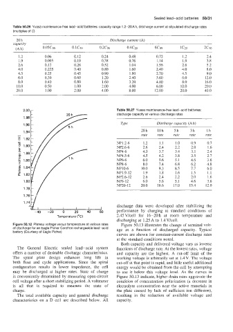
discharge data were developed after stabilizing the
I I I I I I
-40 -20 0 20 40 60 performance by charging at standard conditions Qf
Temperature ("C) 2.45Vkell for 16-20h at room temperature and
discharging at 1.25 A to 1.4 V/cell.
Figure 50.12 Plateau voltage versus temperature at various rates Figure 50.13 illustrates the change of terminal volt-
of discharge for an Eagle Picher Carefree rechargeable lead-acid age as a function of discharged capacity. Typical
battery (Courtesy of Eagle Picher)
curves are shown for constant-current discharge rates
at the standard conditions noted.
Both capacity and delivered voltage vary as inverse
The General Electric sealed lead-acid system functions of discharge rate. At the lowest rates, voltage
offers a number of desirable discharge characteristics. and capacity are the highest. A cut-off limit of the
The spiral plate design enhances long life in working voltage is arbitrarily set at 1.4 V. The voltage
both float and cycle applications. Since the spiral cut-off at that point is rapid, and little useful additional
configuration results in lower impedance, the cell energy would be obtained from the cell by attempting
may be discharged at higher rates. State of charge to use it below this voltage level. As the curves in
is conveniently determined by measuring open-circuit Figure 50.13 indicate, higher drain rates aggravate the
cell voltage after a short stabilizing period. A voltmeter condition of concentration polarization (a decrease in
is all that is required to measure the state of electrolyte concentration near the active materials in
charge. the plate caused by lack of sufficient ion diffusion),
The total available capacity and general discharge resulting in the reduction of available voltage and
characteristics on a D cell are described below. All capacity.