
Page 557 - Battery Reference Book
P. 557
Nickel-cadmium secondary batteries 51/5
(Table 51.1). There is also a special version VRE cell
available for missile applications.
VR cells when continuously discharged at normal
temperatures supply currents of the order shown in
Table 51.2. Short-duration peaks (maximum power)
can be obtained. For example, for 300ms at 0.65 V
" 0.91 5c, = 200 rnh per cell, typical currents are given in Table 51.3.
0.8 I I I I I
0 10 20 30 40
Discharged capacity irnA h) Table 51.2 Continuous discharge
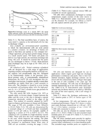
Figure 51.2 Discharge curve of a typical SAF'T VB series Cell type Cell current (A)
nickel-cadmium button cell (continuous discharge at 20 f 5°C).
Maximum permissible continuous rate 200 mA (Courtesy of SAFT) VR 1.2 RR 12
VR2C 14
Table 51.1). The final assemblies have, of course, the VR4D 28
35
VR7F
same rated C5 capacity as the individual cells but vary VR 10 80
in discharge voltage.
Also availablle are environment-proof assemblies
in which the interconnected cells are resin potted
in a plastics container. An advantage of button cell Table 51.3 Short duration discharge
packs is that these can operate as very compact low- peaks
voltage capacitors, giving much greater energy storage Cell type Cell current (A)
in a much smaller space. VB button cell packs can
deliver very high currents, the maximum discharge rate VR 1.2 RR 77
being 10C5mA. It should be ensured that the packs VR2C 93
are not discharged to below IVkell. Short-duration VR4D 145
peak discharges may be as high as 50- lOOCs mA at VR7F 170
0.8 V/cell. VR 10 200
VR cylindrical cells Nickel-cadmium cylindrical
cells are designed for a wide range of applications
requiring compact rechargeable batteries with high out- VR cells and batteries are designed for use in
put capacity and exceptionally long life. Designed applications which require good high-rate discharge
to be dimensionally similar to the principal cylin- performance (continuous and peak). Due to their low
drical primary cells, of internationally standardized internal resistance, higher discharge currents can be
dimensions, the SAFT VR cells incorporate thin sin- drawn and also substantially better voltages than apply
tered plate construction. Complete spirally wound plate in the case of cells available a few years ago. On
assemblies are tightly fitted into a steel container to continuous discharge, VR cells may be discharged at
form cells. The container is closed by a cover having currents representing up to ten times their rated capa-
an automatic self-reclosing safety valve for high pres- city (Table 5 1.4). In short-duration peak discharges
sure (9-14 x IO5 N/m2) should excess gas pressure be currents may be drawn which are as much as 100 times
caused by maltreatment. the value of the rated capacity, with a cell voltage of
The cells satisfy BS 3456: Section 2.36: 1973 as 0.65 Vkell.
regards safety on reverse charge. Contact between the Table 51.5 shows the discharge performance for
plates and the cover or the case is through a special 0.3 s duration peaks at 20°C of various types of VR
connection electrically welded to the edges of the cell.
plates. This method of assembly adopted by SAFT At low temperatures, VR cells and battefies give
improves battey performance on charge and discharge. exceptional performance. Figure 51.3 shows a contin-
The range of VR cells available is from IOOmAh uous peak discharge characteristic at +20 and -20°C
to lOAh (Table 51.1). VR cells are characterized by for a 1.2Ah battery consisting of ten 1.2Ah VR
a nominal voltage of I .2 Vkell and their remarkable 1.2 RR cells connected in series.
power (1.2Ah per cell) is, for example, capable of VR cells can also be obtained in standard battery
supplying a current of 77 A at 0.65 V for 0.3 s. The packs of 2.4-28.8V (Table 51.6) and extended range
cylindrical cell is available in a high-reliability version modular packs of 12 and 24 V (Table 5 1.7), both in a
(VRE). These cells have the cover welded directly on range of capacities.
to the case, which improves the sealing. The plate The VR series standard packs provide for applica-
group is also given supplementary support to increase tions requiring high performance on discharge at large
the resistance to mechanical forces. Four sizes of currents either continuously or in short-duration peaks.
VRE cell are available, covering the range 1-6Ah. The extended range modular packs are supplied in a