
Page 262 - Beyond Decommissioning
P. 262
Experience and lessons learned 243
“The problem of the chimney… is surely a typical example of the many ‘emergen-
cies’ posed by our historical buildings. The evolution in the methods employed in its
making went hand in hand, in Europe, with a progressive transformation of the urban
and rural landscape as a result of industrialization. What’s more, the chimney’s design
and construction often reveals the independent cultural roots of a given geographical
area—tangible signs of the local artisans’ skill” (Riva and Zorgno, 1995). The remark-
able height of some of the surviving chimneys in abandoned industrial areas, and the
valid methods used in their making remain surprising.
As new types of chimneys emerged, the old chimneys were abandoned and soon
aged, often deteriorating to such a point that they were no longer structurally safe.
The problem of preservation of historical chimneys must be approached with great
attention with a focus on material testing and static/dynamic simulations. But industrial
chimneys convey a sense of cultural “belonging,” which should not be disregarded. One
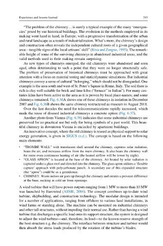
example is the area south and west of St. Peter’s Square in Rome, Italy. The soil there is
rich in clay well suitable for brick and lime kilns (“fornace” in Italian”). For many cen-
turies kilns have been active in the area as it is proven by local place-names; and some
chimneys remained. Fig. 6.36A shows one of these chimneys in isolation in December
2007 and Fig. 6.36B shows the same chimney restructered as museum in August 2018.
Over the last decades the need for telecommunications rapidly increased, which
made the reuse of disused industrial chimneys a concrete option (Fig. 6.37).
Another photo from Vienna (Fig. 6.38) indicates that some industrial chimneys are
preserved for no practical use but only for being symbols of a past world. This beau-
tiful chimney in downtown Vienna is encircled by apartment buildings.
An innovative concept, where the old chimney is reused as physical support to solar
energy generation, is given in SIGUS (n.d.). The concept is based on the following
main elements:
l “TROMBE WALL” with translucent shell around the chimney, captures solar radiation,
heats the air, and increases airflow from the main chimney. It also heats the chimney wall
for more even continuous heating of air (the heated airflow will be lower by night).
l “GLASS APRON” is located at the base of the chimney. Air heated by solar radiation is
captured under a glass roof and directed into the chimney. The glass apron utilizes a ‘flexible
capture’ approach with polycarbonate panels. A secondary use of this expanded structure
(the “apron”) could be as a greenhouse.
l CHIMNEY. Warm indoor air goes up through the chimney and creates a pressure difference
at the base, sucking in cold air from openings.
A wind turbine that will have power outputs ranging from 1 MW to more than 10 MW
was launched by Eurowind (ASME, 2004). The concept combines up-to-date wind
turbine, shipbuilding, and construction technology. The modular design is intended
for a number of applications, ranging from offshore to various land installations, in
wind farms or standing alone. The machine can be mounted on industrial chimneys
and other tall structures, without impeding their normal use. Rather than having a wind
turbine that discharges a specific load onto its support structure, the system is designed
to adjust the wind turbine—and, therefore, its load—to the known reserve strength of
the host structure e.g. the chimney. The interface between structure and turbine would
then absorb the stress loads produced by the rotation of the turbine’s blades.