
Page 268 - Biomass Gasification, Pyrolysis And Torrefaction Practical Design and Theory
P. 268
244 Biomass Gasification, Pyrolysis and Torrefaction
Char gasification, the next critical step, may be assumed to move simulta-
neously through reactions R1, R2, and R3 (Table 7.2). As these three reac-
tions occur simultaneously on the char particle, reducing its mass, the overall
rate is given as:
m char 5 m Boudouard 1 m steam 1 m methanation (7.84)
The conversion of the porous char particle may be modeled assuming
that the process follows shrinking particle (diminishing size), shrinking core
(diminishing size of the unreacted core), or progressive conversion (dimin-
ishing density). The shift reaction is the most important homogenous reaction
followed by steam reforming. The bed materials may catalyze the homoge-
neous reactions, but only in the emulsion phase, because the bubble phase is
assumed to be free of solids.
7.6.3 Entrained-Flow Gasifiers
Extensive work on the modeling of entrained-flow gasifiers is available in
the literature. CFD has been successfully applied to this gasifier type. This
section presents a simplified approach to entrained-flow gasification follow-
ing the work of Vamvuka et al. (1995).
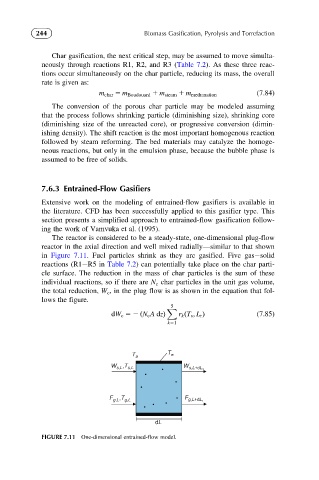
The reactor is considered to be a steady-state, one-dimensional plug-flow
reactor in the axial direction and well mixed radially—similar to that shown
in Figure 7.11. Fuel particles shrink as they are gasified. Five gas solid
reactions (R1 R5 in Table 7.2) can potentially take place on the char parti-
cle surface. The reduction in the mass of char particles is the sum of these
individual reactions, so if there are N c char particles in the unit gas volume,
the total reduction, W c , in the plug flow is as shown in the equation that fol-
lows the figure.
5
X
dW c 52 ðN c A dzÞ r k ðT s ; L r Þ (7.85)
k51
T a T w
W s,L ,T s,L W s,L+dL,
F g,L ,T g,L F g,L+dL,
dL
FIGURE 7.11 One-dimensional entrained-flow model.