
Page 226 - Biosystems Engineering
P. 226
204 Cha pte r S i x
the maximum rate at the beginning of the irrigation and cuts back the
flow when the advancing waterfront reaches the end of the field. All
dry soils initially absorb water rapidly, and once the soil near the sur-
face begins to swell, infiltration declines. Therefore, a well-designed
system should have the capability to cut back the water flow to the
furrow after the initial surge in application. The cablegation system
achieves this automatically based on gravity flow.
Sprinkler Irrigation Systems
Sprinkler irrigation systems have been very popular due to their low
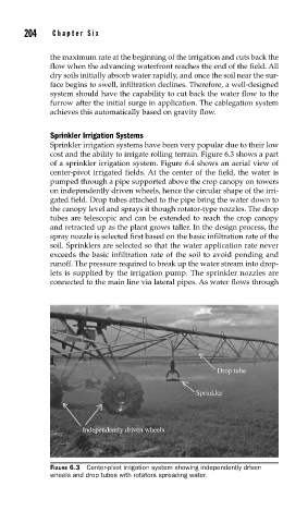
cost and the ability to irrigate rolling terrain. Figure 6.3 shows a part
of a sprinkler irrigation system. Figure 6.4 shows an aerial view of
center-pivot irrigated fields. At the center of the field, the water is
pumped through a pipe supported above the crop canopy on towers
on independently driven wheels, hence the circular shape of the irri-
gated field. Drop tubes attached to the pipe bring the water down to
the canopy level and sprays it though rotator-type nozzles. The drop
tubes are telescopic and can be extended to reach the crop canopy
and retracted up as the plant grows taller. In the design process, the
spray nozzle is selected first based on the basic infiltration rate of the
soil. Sprinklers are selected so that the water application rate never
exceeds the basic infiltration rate of the soil to avoid ponding and
runoff. The pressure required to break up the water stream into drop-
lets is supplied by the irrigation pump. The sprinkler nozzles are
connected to the main line via lateral pipes. As water flows through
Drop tube
Sprinkler
Independently driven wheels
FIGURE 6.3 Center-pivot irrigation system showing independently driven
wheels and drop tubes with rotators spreading water.