
Page 238 - Bridge and Highway Structure Rehabilitation and Repair
P. 238
CHAPTER 5 LOAD AND RESISTANCE FACTOR RATING AND REDESIGN 213
(KN)
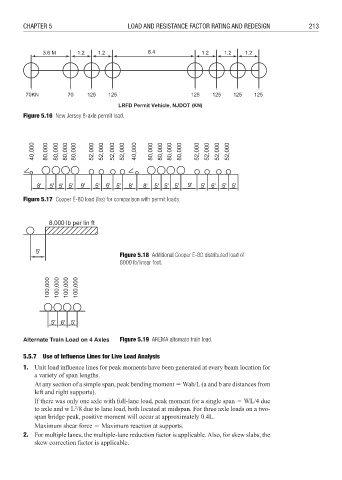
Figure 5.16 New Jersey 8-axle permit load.
Figure 5.17 Cooper E-80 load (lbs) for comparison with permit loads.
Figure 5.18 Additional Cooper E-80 distributed load of
8000 lb/linear foot.
Figure 5.19 AREMA alternate train load.
5.5.7 Use of Influence Lines for Live Load Analysis
1. Unit load influence lines for peak moments have been generated at every beam location for
a variety of span lengths.
At any section of a simple span, peak bending moment 3 Wab/L (a and b are distances from
left and right supports).
If there was only one axle with full-lane load, peak moment for a single span 3 WL/4 due
2
to axle and w L /8 due to lane load, both located at midspan. For three axle loads on a two-
span bridge peak, positive moment will occur at approximately 0.4L.
Maximum shear force 3 Maximum reaction at supports.
2. For multiple lanes, the multiple-lane reduction factor is applicable. Also, for skew slabs, the
skew correction factor is applicable.