
Page 178 - Build Your Own Combat Robot
P. 178
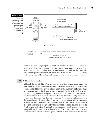
FIGURE  8-1                                     Chapter 8:  Remotely Controlling Your Robot  159
                             Wiring and
                         rotational position
                        of R/C servos as a
                           function of the
                             pulse-width
                             commands.


                                    between the two). A signal pulse is sent from the radio receiver to each servo ap-
                                    proximately 50 times per second. The exact pulse frequency can vary from 50 to
                                    60 times a second, depending on the manufacturer and model of the radio. The
                                    length of the pulse encodes the movement data in the range of 1.0 to 2.0 millisec-
                                    onds, with a pulse of 1.5 milliseconds being a neutral or center position command.


                                The R/C Controller’s Interface
                                    Although the electrical interface has been standardized, manufacturers use their
                                    own color codes and connectors to attach the radio receiver to the servos. The
                                    color-coding of the wires always follows a similar motif: the ground wire is black
                                    or brown; the power line is almost always red; and the signal line will be white,
                                    yellow, orange, or occasionally black. The order of the control pins is the same in
                                    nearly all manufacturers’ units—the wire closest to the notched edge of the radio
                                    connector is the signal wire, the center wire is the 5-volt power, and the last wire is
                                    the ground wire. (Airtronics brand connectors use a unique wire arrangement
                                    that’s worth mentioning here. The wire next to the notched side of the connector is
                                    the signal wire (blue), the ground wire is in the middle (black), and next is the
                                    5-volt power (red) wire.) Electrically speaking, most manufacturers’ systems are
                                    compatible, so the connectors can be easily cut off and swapped with another style
                                    of connector to convert servos or speed controllers from one system to another.