
Page 195 - Build Your Own Combat Robot
P. 195
Build Your Own Combat Robot
176
The “PWM” outputs are the same type of 1- to 2-millisecond signals that R/C
servos and electronic speed controllers such as the Victor 883, Vantec, and tradi-
tional R/C car ESCs, understand. With this system, you could control 16 different
high-powered motors—double the number of motors you could control with
top-of-the-line traditional R/C systems. Then you can add up to 16 additional re-
lay controls for weapons, actuators, lights, or just about anything else you would
like to control.
What makes this system different from traditional R/C systems is its ability to
analyze digital and analog inputs. In your robot, you could include tachometers
on the motors to monitor actual rotational speed to implement closed-loop speed
control. You could add thermocouples or resistive temperature sensors to the motor
housing to monitor the temperature of the motors and help prevent them from
overheating. In the robot controller is a Basic Stamp that can be programmed to
read in the input values and send signals out to control the corresponding actions
of the robot. Not only can the robot perform some semiautonomous actions, but
the robot controller can send back information to the main operator interface so
that the operator can be notified what the robot is doing internally. One set of data
could be a self-diagnosis to monitor the health of the robot during a combat
match, and you could even monitor the charge on the batteries in real time.
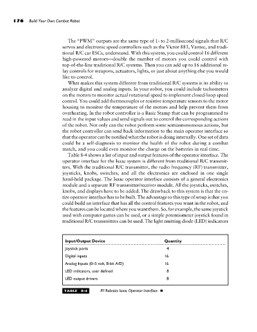
Table 8-4 shows a list of input and output features of the operator interface. The
operator interface for the Isaac system is different from traditional R/C transmit-
ters. With the traditional R/C transmitter, the radio frequency (RF) transmitter,
joysticks, knobs, switches, and all the electronics are enclosed in one single
hand-held package. The Isaac operator interface consists of a general electronics
module and a separate RF transmitter/receiver module. All the joysticks, switches,
knobs, and displays have to be added. The drawback to this system is that the en-
tire operator interface has to be built. The advantage to this type of setup is that you
could build an interface that has all the control features you want in the robot, and
the features can be located where you want them. So, for example, the same joystick
used with computer games can be used, or a simple potentiometer joystick found in
traditional R/C transmitters can be used. The light emitting diode (LED) indicators
Input/Output Device Quantity
Joystick ports 4
Digital inputs 16
Analog Inputs (0–5 volt, 8-bit A/D) 16
LED indicators, user defined 8
LED output drivers 8
TABLE 8-4 IFI Robotics Isaac Operator Interface