
Page 148 - Buried Pipe Design
P. 148
122 Chapter Three
W
Unit Wt. P H
d H
of Soil
s y
2r P s x
A Live Load A x
D
r X r s y
Pipe Walls are Cladding
For the Soil Column
X
Section AA
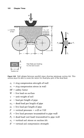
Figure 3.26 Soil column between parallel pipes showing minimum section AA. This
section must be able to resist the entire live load plus part of the dead load.
f ring compression strength of wall
t ring compression stress in wall
SF safety factor
W live load on surface
unit weight of soil
w load per length of pipe
w d dead load per length of pipe
w l live load per length of pipe
P vertical pressure w/D or V/D
P l live load pressure transmitted to pipe wall
P d dead load (soil load) transmitted to pipe wall
y vertical soil stress on section AA
S′ vertical soil compression strength