
Page 81 - Buried Pipe Design
P. 81
External Loads 57
Frost Loading
When freezing atmospheric conditions exist continuously for several
hours, ice layers or lenses form as shallow soil moisture freezes. As
the frost penetrates downward, additional small volumes of water
freeze. This freezing has a drying effect upon the soil since the water
is no longer available to satisfy the soil’s attraction for capillary
water. Thus, groundwater from below the frost layer is attracted by
capillary action to the area of lower potential. This water also freezes
as it reaches the frost, and the process continues until equilibrium is
reached. The freezing of ice below existing ice layers causes pressure
to develop because of the expansion due to growth (volume increase)
of ice.
It has been shown that this expansive pressure can substantially
increase vertical loads on buried pipes. A paper authored by W. Harry
Smith (AWWA Journal, December 1975) indicates almost a doubling of
load during the deepest frost penetration. For this study, the test pipe
setup was essentially nonyielding.
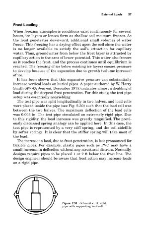
The test pipe was split longitudinally in two halves, and load cells
were placed inside the pipe (see Fig. 2.30) such that the load cell was
between the two halves. The maximum deflection of the load cells
was 0.003 in. The test pipe simulated an extremely rigid pipe. Due
to this rigidity, the load increase was greatly magnified. The previ-
ously discussed spring analogy can be applied here. In this case, the
test pipe is represented by a very stiff spring, and the soil sidefills
by softer springs. It is clear that the stiffer spring will take most of
the load.
The increase in load, due to frost penetration, is less pronounced for
flexible pipes. For example, plastic pipes such as PVC may have a
small increase in deflection without any structural distress. Normally,
designs require pipes to be placed 1 or 2 ft below the frost line. The
design engineer should be aware that frost action may increase loads
on a rigid pipe.
Figure 2.30 Schematic of split
pipe with supporting load cell.