
Page 195 - CNC Robotics
P. 195
CNC Robotics
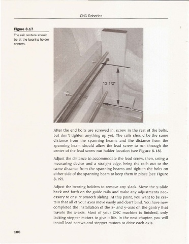
Agure 8.17
The rail centers should
be at the bearing holder
centers.
13 1/2"
After the end bolts are screwed in. screw in the rest of the bolts.
but don't tighten anything up yet. The rail s should be the same
distance from the spanning beams and the distance from the
spanning beam should allow the lead screw to ru n through the
center of the lead screw nut holder location (see Figure 8. 18).
Adj ust the distance to accommo date the lead screw. then. using a
measuring device and a straig ht edge. bring the rails out to the
same distance from the spanning beams and tighten the bo lts on
either side of the span ni ng beam to keep them in place (see Figure
8. 19).
Adjust the bearing ho lders to remove any slack. Move the y-slide
back and forth on th e guide rails and make any adjustm ents nec-
essary to ensure smooth sliding. At this point, yo u wa nt to be cer-
tain that all of your axes move easily and don't bind. You have now
completed the in stallation of the z- and y-axis on the gantry that
travels the x-axis, Mo st of your CNC machine is finished. only
lacking stepper motors to give it life. In the next chapter, you w ill
install lead screws an d stepper motors to drive each axis.
186