
Page 205 - CNC Robotics
P. 205
CNC Robotics
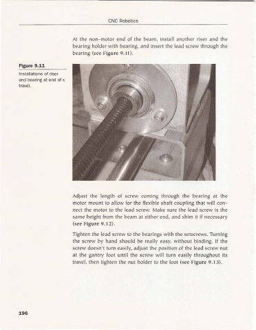
At the non-motor end of the beam. install another riser and the
bearing holder with bearing. and insert the lead screw through the
beari ng (see Figure 9.11).
Figure 9.11
Installations of riser
and bea ring at end of x
travel.
Adjust the length of screw com ing through the bea ring at the
motor mount to allow for the flexible shaft coupling that will con-
nect the motor to the lead screw. Make sure the lead screw is the
sa me height from the beam at either end. and shim it if necessary
(see Figure 9.12).
Tighten the lead screw to the bearings with the setscrews. Turni ng
the screw by ha nd shou ld be really easy. without binding. If the
screw doesn't tu rn easily, ad just the position of the lead screw nut
at the gantry foot until the screw will turn easily thro ughout its
travel. then tighten the nut ho lder to the foot (see Figure 9.13).
196