
Page 382 - Caldera Volcanism Analysis, Modelling and Response
P. 382
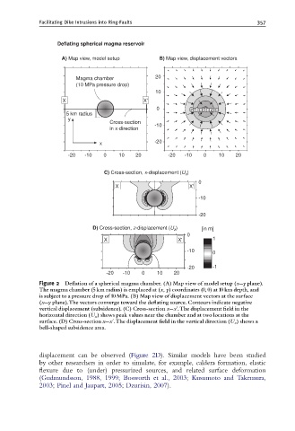
Facilitating Dike Intrusions into Ring-Faults                        357


                   Deflating spherical magma reservoir

                     A) Map view, model setup      B) Map view, displacement vectors


                         Magma chamber            20
                         (10 MPa pressure drop)
                                                  10
                     5 X                      X'
                                                   0         Subsidence
                                                             Subsidence
                                                             Subsidence
                      5 km radius
                       y
                                    Cross-section
                                                  -10
                                    in x-direction
                                 x                -20
                       -20  -10   0    10   20        -20  -10   0    10    20


                                                            )
                                  C) Cross-section, x-displacement (U x
                                                                0
                                      X                      X'
                                                                -10

                                                                -20
                                                         )
                              D) Cross-section, z-displacement (U z  [in m]
                                                            0
                                  X                      X'         1
                                                            -10     0

                                                            -20     -1
                                   -20  -10   0    10   20
             Figure 2  De£ation of a spherical magma chamber. (A) Map view of model setup (x--y plane).
             The magma chamber (5 km radius) is emplaced at (x, y) coordinates (0, 0) at 10 km depth, and
             is subject to a pressure drop of 10 MPa. (B) Map view of displacement vectors at the surface
             (x--y plane).The vectors converge toward the de£ating source. Contours indicate negative
             vertical displacement (subsidence). (C) Cross-section x--xu.The displacement ¢eld in the
             horizontal direction (U x ) shows peak values near the chamber and at two locations at the
             surface. (D) Cross-section x--xu.The displacement ¢eld in the vertical direction (U z ) shows a
             bell-shaped subsidence area.


             displacement can be observed (Figure 2D). Similar models have been studied
             by other researchers in order to simulate, for example, caldera formation, elastic
             flexure due to (under) pressurized sources, and related surface deformation
             (Gudmundsson, 1988, 1999; Bosworth et al., 2003; Kusumoto and Takemura,
             2003; Pinel and Jaupart, 2005; Dzurisin, 2007).