
Page 170 - Centrifugal Pumps 2E
P. 170
150 Centrifugal Pumps: Design and Application
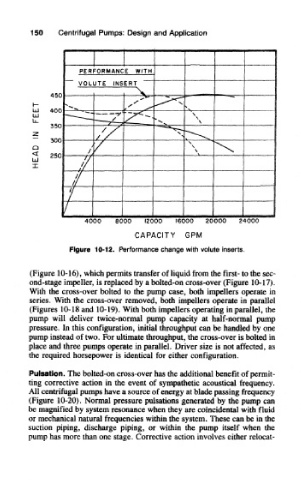
Figure 10-12. Performance change with volute inserts.
(Figure 10-16), which permits transfer of liquid from the first- to the sec-
ond-stage impeller, is replaced by a bolted-on cross-over (Figure 10-17).
With the cross-over bolted to the pump case, both impellers operate in
series. With the cross-over removed, both impellers operate in parallel
(Figures 10-18 and 10-19). With both impellers operating in parallel, the
pump will deliver twice-normal pump capacity at half-normal pump
pressure. In this configuration, initial throughput can be handled by one
pump instead of two. For ultimate throughput, the cross-over is bolted in
place and three pumps operate in parallel. Driver size is not affected, as
the required horsepower is identical for either configuration.
Pulsation. The bolted-on cross-over has the additional benefit of permit-
ting corrective action in the event of sympathetic acoustical frequency.
All centrifugal pumps have a source of energy at blade passing frequency
(Figure 10-20). Normal pressure pulsations generated by the pump can
be magnified by system resonance when they are coincidental with fluid
or mechanical natural frequencies within the system. These can be in the
suction piping, discharge piping, or within the pump itself when the
pump has more than one stage. Corrective action involves either relocat-