
Page 18 - Centrifugal Pumps 2E
P. 18
6 Centrifugal Pumps: Design and Application
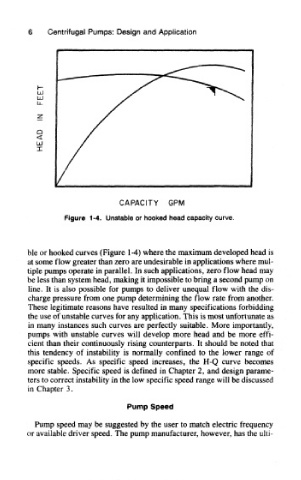
Figure 1-4. Unstable or hooked head capacity curve.
ble or hooked curves (Figure 1-4) where the maximum developed head is
at some flow greater than zero are undesirable in applications where mul-
tiple pumps operate in parallel. In such applications, zero flow head may
be less than system head, making it impossible to bring a second pump on
line. It is also possible for pumps to deliver unequal flow with the dis-
charge pressure from one pump determining the flow rate from another.
These legitimate reasons have resulted in many specifications forbidding
the use of unstable curves for any application. This is most unfortunate as
in many instances such curves are perfectly suitable. More importantly,
pumps with unstable curves will develop more head and be more effi-
cient than their continuously rising counterparts. It should be noted that
this tendency of instability is normally confined to the lower range of
specific speeds. As specific speed increases, the H-Q curve becomes
more stable. Specific speed is defined in Chapter 2, and design parame-
ters to correct instability in the low specific speed range will be discussed
in Chapter 3.
Pump Speed
Pump speed may be suggested by the user to match electric frequency
or available driver speed. The pump manufacturer, however, has the ulti