
Page 308 - Centrifugal Pumps 2E
P. 308
Hydraulic Power Recovery Turbines 275
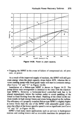
Figure 14-20. Power vs. plant capacity.
• Tripping the HPRT in the event of failure of compressed air, oil pres-
sure, or power.
As a result of the improved supply of medium, the HPRT will still gen-
erate energy when the plant capacity drops below 40%, whereas the re-
verse running pump with fixed guide vanes will start to consume energy.
(See Curve "A" and "C" in Figure 14-20).
Installation of a Pelton-type HPRT is shown in Figure 14-22. The
pump-driver train arrangement is identical to the ones with the reaction-
type HPRT's. However, a horizontal-level controlled tank has to be
placed immediately below the turbine outlet to avoid paddling of the
wheel in fluid flowing from the wheel. Paddling of the wheel in the me-
dium results in high energy losses and strain being placed on the turbine.
The efficiency of a properly installed Pelton-type HPRT is slightly higher
at lower flows than the one of the HPRT with adjustable guide vanes,
since the effect of the lower specific speed is not as significant (see Curve
"A" and "D" in Figure 14-20).
HPRT's find many more applications such as services in hydropower
stations and cooling towers and as reversible machines for pumped stor-