
Page 329 - Centrifugal Pumps 2E
P. 329
294 Centrifugal Pumps: Design and Application
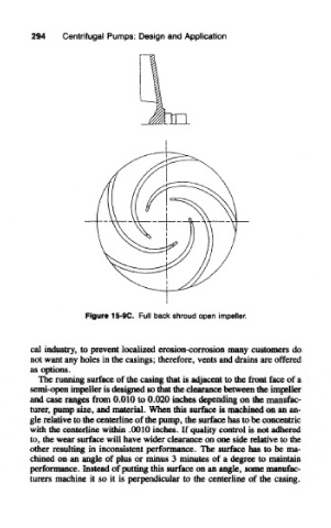
Figure 15-9C. Full back shroud open impeller.
cal industry, to prevent localized erosion-corrosion many customers do
not want any holes in the casings; therefore, vents and drains are offered
as options.
The running surface of the casing that is adjacent to the front face of a
semi-open impeller is designed so mat the clearance between the impeller
and case ranges from 0.010 to 0.020 inches depending on the manufac-
turer, pump size, and material. When this surface is machined on an an-
gle relative to the centerline of the pump, the surface has to be concentric
with the centerline within .0010 inches. If quality control is not adhered
to, the wear surface will have wider clearance on one side relative to the
other resulting in inconsistent performance. The surface has to be ma-
chined on an angle of plus or minus 3 minutes of a degree to maintain
performance. Instead of (Hitting this surface on an angle, some manufac-
turers machine it so it is perpendicular to the centerline of the casing.