
Page 357 - Centrifugal Pumps 2E
P. 357
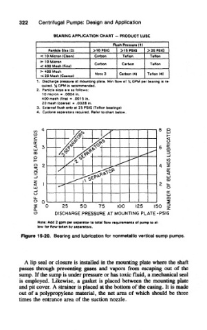
322    Centrifugal Pumps: Design and Application

                     BEARING APPLICATION CHART - PRODUCT LUBE
                                            Rush Pressure (1)
                   Particle Six* (2)  > 10 PSIG  >16PSIG  > 25 PSIG
                -CIO Micron (Clean)  Carbon     Teflon    Teflon
                >• 1 0 Micron        Carbon    Carbon     Teflon
                <: 400 Mesh (Fine)
                >• 400 Mesh          Note 3   Carbon (4|  Teflon (4)
                < 20 Mesh (Coarse)
               1. Discharge pressure at mounting plate. Min flow of % GPM per bearing is re-
                 quired. % GPM is recommended,
               2. Particle sizes are as follows:
                 10 micron - .0004 in.
                 400 mesh (fine) - .0015 in.
                 20 mesh (coarse) * .0328 in.
               3, Exttrnat flush only at 25 PSIG (Teflon bearings)
               4, Cyclone separators required. Refer to chart below.


         Figure 15-20. Bearing and lubrication for nonmetallic vertical sump pumps.


          A lip seal or closure is installed in the mounting plate where the shaft
        passes through preventing gases and vapors from escaping out of the
        sump. If the sump is under pressure or has toxic fluid, a mechanical seal
        is employed. Likewise, a gasket is placed between the mounting plate
        and pit cover. A strainer is placed at the bottom of the casing. It is made
        out of a polypropylene material, the net area of which should be three
        times the entrance area of the suction nozzle.