
Page 97 - Centrifugal Pumps 2E
P. 97
Double-Suction Pumps 81
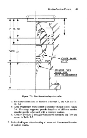
Figure 7-3. Double-suction layout—profile.
a. For linear dimensions of Sections 1 through 7, and A-B, use Ta-
ble 7-1.
b. Area progression from nozzle to impeller should follow Figure
7-4. The range suggested permits impellers of different suction
specific speeds to be used with a common suction.
c. Areas of Sections 3 through 6 measured normal to the flow are
shown in Table 7-2.
2. Make final layout after checking all areas and dimensional location
of suction nozzle.