
Page 296 - Centrifugal Pumps Design and Application
P. 296
264 Centrifugal Pumps: Design and Application
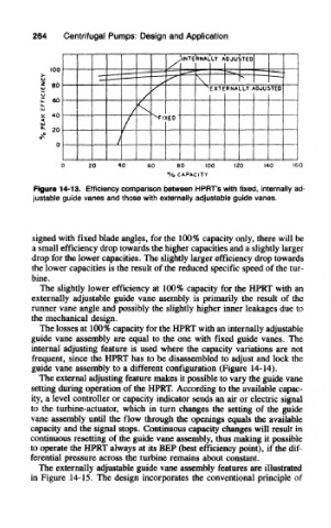
Figure 14-13. Efficiency comparison between HPRT's with fixed, internally ad-
justable guide vanes and those with externally adjustable guide vanes.
signed with fixed blade angles, for the 100% capacity only, there will be
a small efficiency drop towards the higher capacities and a slightly larger
drop for the lower capacities. The slightly larger efficiency drop towards
the lower capacities is the result of the reduced specific speed of the tur-
bine.
The slightly lower efficiency at 100% capacity for the HPRT with an
externally adjustable guide vane asembly is primarily the result of the
runner vane angle and possibly the slightly higher inner leakages due to
the mechanical design.
The losses at 100% capacity for the HPRT with an internally adjustable
guide vane assembly are equal to the one with fixed guide vanes. The
internal adjusting feature is used where the capacity variations are not
frequent, since the HPRT has to be disassembled to adjust and lock the
guide vane assembly to a different configuration (Figure 14-14).
The external adjusting feature makes it possible to vary the guide vane
setting during operation of the HPRT. According to the available capac-
ity, a level controller or capacity indicator sends an air or electric signal
to the turbine-actuator, which in turn changes the setting of the guide
vane assembly until the flow through the openings equals the available
capacity and the signal stops. Continuous capacity changes will result in
continuous resetting of the guide vane assembly, thus making it possible
to operate the HPRT always at its BEP (best efficiency point), if the dif-
ferential pressure across the turbine remains about constant.
The externally adjustable guide vane assembly features are illustrated
in Figure 14-15. The design incorporates the conventional principle of