
Page 160 - Chalcogenide Glasses for Infrared Optics
P. 160
136 Cha pte r S i x
The large aluminum chamber is equipped with a door that may be
sealed, and the chamber evacuated down to a pressure of 50 µm or
less. Inside was placed a standard inexpensive programmable oven
equipped with a blower to provide circulating air. The temperatures
of the molds are controlled using band heaters. The glass blank is
placed in the mold, the door is closed, and the unit is evacuated. The
molds and glass blank are heated to the molding temperature, and
pressure is applied from the cylinder on top of the unit. A few hun-
dred pounds of force is needed for lenses with 1- to 2-in diameter with
less than 1000 lb for lenses with almost 6-in diameter. A linear gauge
indicates when the molds are closed, indicating the lens is formed.
The molds and lens are cooled slightly, the pressure is released, and
the unit is vented. After the door is opened, the oven is turned on and
the glass anneal cycle is started.
As results improved, a plan was devised by LMC to prove the
quality of molded chalcogenide glass optics was equal to that of those
made by diamond point turning (DPT). A 100-mm FL, F/0.8, 10° field
of view, two-element lens was designed using Amtir 4 for use with a
LTC 500 LWIR uncooled bolometer array camera produced by a
Lockheed Martin company. The front element had a 4.6-in diameter.
The convex surfaces of both lenses were spherical. The concave
surfaces were aspheric with kinoforms. The first set of optics was
diamond turned and coated at AMI. The second was molded and
1
coated at AMI. Amy Graham of LMCO showed thermal images that
demonstrated that optical performance of the camera using the
molded lenses was essentially the same as when using the DPT lenses.
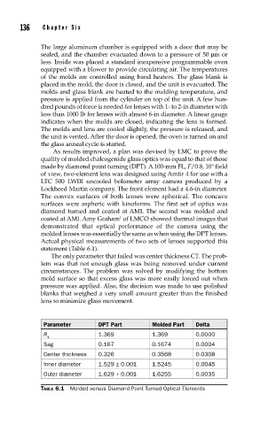
Actual physical measurements of two sets of lenses supported this
statement (Table 6.1).
The only parameter that failed was center thickness CT. The prob-
lem was that not enough glass was being removed under current
circumstances. The problem was solved by modifying the bottom
mold surface so that excess glass was more easily forced out when
pressure was applied. Also, the decision was made to use polished
blanks that weighed a very small amount greater than the finished
lens to minimize glass movement.
Parameter DPT Part Molded Part Delta
R 1.369 1.369 0.0000
1
Sag 0.167 0.1674 0.0004
Center thickness 0.326 0.3568 0.0308
Inner diameter 1.529 ± 0.001 1.5245 0.0045
Outer diameter 1.629 + 0.001 1.6255 0.0035
TABLE 6.1 Molded versus Diamond Point Turned Optical Elements