
Page 254 - Challenges in Corrosion Costs Causes Consequences and Control(2015)
P. 254
232 CORROSION CONTROL AND PREVENTION
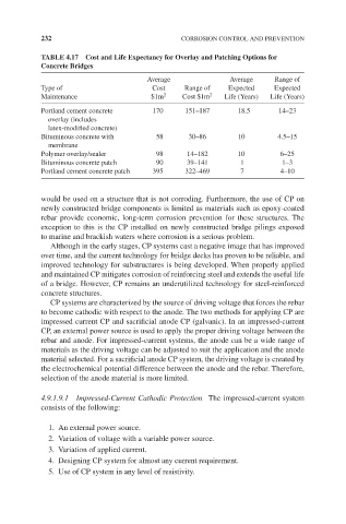
TABLE 4.17 Cost and Life Expectancy for Overlay and Patching Options for
Concrete Bridges
Average Average Range of
Type of Cost Range of Expected Expected
Maintenance $1m 2 Cost $1m 2 Life (Years) Life (Years)
Portland cement concrete 170 151–187 18.5 14–23
overlay (includes
latex-modified concrete)
Bituminous concrete with 58 30–86 10 4.5–15
membrane
Polymer overlay/sealer 98 14–182 10 6–25
Bituminous concrete patch 90 39–141 1 1–3
Portland cement concrete patch 395 322–469 7 4–10
would be used on a structure that is not corroding. Furthermore, the use of CP on
newly constructed bridge components is limited as materials such as epoxy-coated
rebar provide economic, long-term corrosion prevention for these structures. The
exception to this is the CP installed on newly constructed bridge pilings exposed
to marine and brackish waters where corrosion is a serious problem.
Although in the early stages, CP systems cast a negative image that has improved
over time, and the current technology for bridge decks has proven to be reliable, and
improved technology for substructures is being developed. When properly applied
and maintained CP mitigates corrosion of reinforcing steel and extends the useful life
of a bridge. However, CP remains an underutilized technology for steel-reinforced
concrete structures.
CP systems are characterized by the source of driving voltage that forces the rebar
to become cathodic with respect to the anode. The two methods for applying CP are
impressed current CP and sacrificial anode CP (galvanic). In an impressed-current
CP, an external power source is used to apply the proper driving voltage between the
rebar and anode. For impressed-current systems, the anode can be a wide range of
materials as the driving voltage can be adjusted to suit the application and the anode
material selected. For a sacrificial anode CP system, the driving voltage is created by
the electrochemical potential difference between the anode and the rebar. Therefore,
selection of the anode material is more limited.
4.9.1.9.1 Impressed-Current Cathodic Protection The impressed-current system
consists of the following:
1. An external power source.
2. Variation of voltage with a variable power source.
3. Variation of applied current.
4. Designing CP system for almost any current requirement.
5. Use of CP system in any level of resistivity.