
Page 195 - Chemical process engineering design and economics
P. 195
Process Heat Transfer 177
Example 4.2 Sizing a Distilled-Water Interchanger_______________
Distilled water at 34 °C is cooled to 30 °C by a raw-water feed at 23 °C flowing to
an evaporator. Estimate the heat-transfer area required to cool 79,500 kg/h
5
(8.16xl0 Ib/h) of distilled water using a 1-2 heat exchanger.
The Equations listed in Table 4.5 can be solved one at a time. Table 4.6 out-
lines the calculation procedure. From Equations 4.5.1, 4.5.2, 4.5.6, and 4.5.7 in
Table 4.5, and noting that the enthalpy difference is equal to C P (t 3i2 -1^), we find
that the heat transferred,
Q = m 3 (h 3, 2 - Ii4, 2) = m 3 C p (t 3;2 -t,,;,)
where the first subscript 3 refers to the entering distilled water stream, and 4 refers
to the exit distilled water stream. The second subscript 2 refers to distilled water,
and the subscript 1 refers to raw water.
3
Q = (79500 kg/h) (lh/3600s) (4.187xl0 J/kg-°C) (34 - 30) °C
6
5
= 3.699xl0 J/s (1.26xl0 Btu/h)
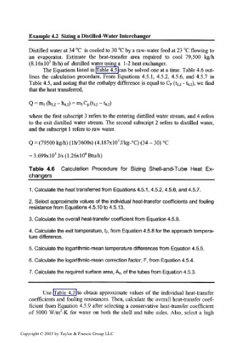
Table 4.6 Calculation Procedure for Sizing Shell-and-Tube Heat Ex-
changers___________________________________
1. Calculate the heat transferred from Equations 4.5.1,4.5.2,4.5.6, and 4.5.7.
2. Select approximate values of the individual heat-transfer coefficients and fouling
resistance from Equations 4.5.10 to 4.5.13.
3. Calculate the overall heat-transfer coefficient from Equation 4.5.9.
4. Calculate the exit temperature, iz, from Equation 4.5.8 for the approach tempera-
ture difference.
5. Calculate the logarithmic-mean temperature differences from Equation 4.5.5.
6. Calculate the logarithmic-mean correction factor, F, from Equation 4.5.4.
7. Calculate the required surface area, AO, of the tubes from Equation 4.5.3.
Use Table 4.3 to obtain approximate values of the individual heat-transfer
coefficients and fouling resistances. Then, calculate the overall heat-transfer coef-
ficient from Equation 4.5.9 after selecting a conservative heat-transfer coefficient
2
of 5000 W/m -K for water on both the shell and tube sides. Also, select a high
Copyright © 2003 by Taylor & Francis Group LLC