
Page 236 - Chemical process engineering design and economics
P. 236
Compressors, Pumps, and Turbines 217
Optimum Compression Ratio
When compressing a gas to a high pressure, the compressor may be divided into
two or more stages. The pressure ratio per stage for various compressors are given
in Table 5.4. The pressure ratio for a compression stage is determined by me-
chanical considerations and is the concern of mechanical engineers. If the gas
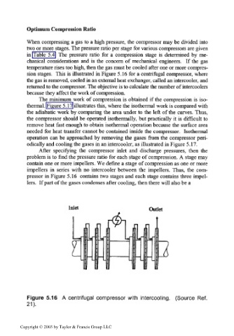
temperature rises too high, then the gas must be cooled after one or more compres-
sion stages. This is illustrated in Figure 5.16 for a centrifugal compressor, where
the gas is removed, cooled in an external heat exchanger, called an intercooler, and
returned to the compressor. The objective is to calculate the number of intercoolers
because they affect the work of compression.
The minimum work of compression is obtained if the compression is iso-
thermal. Figure 5.17 illustrates this, where the isothermal work is compared with
the adiabatic work by comparing the area under to the left of the curves. Thus,
the compressor should be operated isothermally, but practically it is difficult to
remove heat fast enough to obtain isothermal operation because the surface area
needed for heat transfer cannot be contained inside the compressor. Isothermal
operation can be approached by removing the gases from the compressor peri-
odically and cooling the gases in an intercooler, as illustrated in Figure 5.17.
After specifying the compressor inlet and discharge pressures, then the
problem is to find the pressure ratio for each stage of compression. A stage may
contain one or more impellers. We define a stage of compression as one or more
impellers in series with no intercooler between the impellers. Thus, the com-
pressor in Figure 5.16 contains two stages and each stage contains three impel-
lers. If part of the gases condenses after cooling, then there will also be a
Inlet Outlet
L
Figure 5.16 A centrifugal compressor with intercooling. (Source Ref.
21).
Copyright © 2003 by Taylor & Francis Group LLC