
Page 210 - Civil Engineering Formulas
P. 210
CONCRETE FORMULAS 145
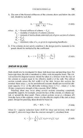
1. The sum of the flexural stiffnesses of the columns above and below the slab
K should be such that
c
K c
c min (5.102)
(K s K b )
where K flexural stiffness of column E I
c cc c
E modulus of elasticity of column concrete
cc
I moment of inertia about centroidal axis of gross section of column
c
K E I
s cs s
K E I
cb b
b
minimum value of as given in engineering handbooks
min c
2. If the columns do not satisfy condition 1, the design positive moments in the
panels should be multiplied by the coefficient:
2 a c
s 1 1 (5.103)
4 a min
SHEAR IN SLABS
Slabs should also be investigated for shear, both beam type and punching shear. For
beam-type shear, the slab is considered as a thin, wide rectangular beam. The crit-
ical section for diagonal tension should be taken at a distance from the face of
the column or capital equal to the effective depth d of the slab. The critical
section extends across the full width b of the slab. Across this section, the
nominal shear stress v on the unreinforced concrete should not exceed the ulti-
u
mate capacity 2 f c or the allowable working stress 1.1 f c , where f c is the
2
28-day compressive strength of the concrete, lb/in (MPa).
Punching shear may occur along several sections extending completely
around the support, for example, around the face of the column, or column cap-
ital, or around the drop panel. These critical sections occur at a distance d/2
from the faces of the supports, where d is the effective depth of the slab or drop
panel. Design for punching shear should be based on
V n (V c V S ) (5.104)
where capacity reduction factor (0.85 for shear and torsion), with shear
strength V taken not larger than the concrete strength V calculated from
c
n
4
V c 2 2 c b o d 4 2 c b o d (5.105)
f
f
c