Page 240 - Civil Engineering Formulas
P. 240

174                     CHAPTER SIX

           For either uniaxial or biaxial bending, f should not exceed
                                       c
                                        K cE E
                                 F cE1                          (6.56)
                                       (L e1 /d 1 ) 2
           where E  is the modulus of elasticity multiplied by adjustment factors. Also, for
           biaxial bending, f should not exceed
                       c
                                        K cE E
                                 F cE2                          (6.57)
                                       (L e2  /d 2 ) 2
           and f should not be more than
              b1
                                        K bE E
                                  F bE                          (6.58)
                                          2
                                         R B
           where d is the width of the wide face and d is the width of the narrow face.
                 1
                                            2
           Slenderness ratio R for beams is given earlier in this section. K bE  is defined
                         B
           earlier in this section. The effective column lengths L for buckling in the d direc-
                                                e1
                                                               1
           tion and L for buckling in the d direction, E , F , and F cE2  should be determined
                  e2
                                            cE1
                                 2
           as shown earlier.
             As for the case of combined bending and axial tension,  F  c  ,  F  b1  , and  F  b2
           should be adjusted for duration of load by applying C .
                                                 D
             Nomenclature for Formulas given in Eqs. (6.59) through (6.57):
               Q   allowable load, lb
               P   ultimate load, lb
               A   section area of column, sq in
               L   length of column, in
               r   least radius of gyration of column section, in
              S   ultimate strength, psi
               u
              S   yield point or yield strength of material, psi
               y
               E   modulus of elasticity of material, psi
               m   factor of safety
            (L/r)   critical slenderness ratio
           SOLID RECTANGULAR OR SQUARE
           COLUMNS WITH FLAT ENDS*
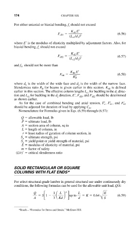
           For select structural-grade lumber in general structural use under continuously dry
           conditions, the following formulas can be used for the allowable unit load, Q/A:
                                     4
                     Q         1            L            E
                                  L
                         S 1           up to     K   0.64       (6.59)
                     A         3  Kd        d          BS
             *Roark—“Formulas for Stress and Strain,” McGraw-Hill.
   235   236   237   238   239   240   241   242   243   244   245