Page 388 - Complete Wireless Design
P. 388

Communications System Design


                                                                   Communications System Design  387


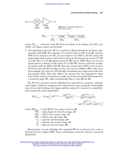
                                                       Figure 9.2 Cascaded stages for
                                                       IP3 calculations.

                                                               1
                                        IP
                                          TOT    1     GAIN      GAIN   GAIN
                                                                      1
                                                             1
                                                                               2
                                                IP3     IP3           IP3
                                                   1        2            3
                        where IP      receiver’s total IP3 from its input to its output and IP3 and
                                 TOT                                                       n
                        GAIN are linear terms, not decibels.
                              n
                        4. The importance of a low NF in a receiver is demonstrated by its linear rela-
                           tionship with SNR. For instance, if a receiver has an NF of 12 dB, and the
                           SNR at its output is 20 dB, we can improve the SNR to 30 dB (using the
                           same input signal power and receiver gain) by decreasing the receiver’s NF
                           to 2 dB. This is a 10-dB improvement in NF and in SNR. Thus, if a certain
                           signal power is placed at the input of a 5-dB NF receiver, and this creates
                           an output with an SNR of 20 dB, then the actual input SNR to the receiver
                           will have been 25 dB. In other words, the receiver added 5 dB to the noise
                           at its output: the receiver’s NF directly correlated into a decrease in the out-
                           put signal’s SNR. This also affects the power that the transmitter must
                           send to the receiver’s antenna to make up for the decreased SNR caused by
                           a receiver’s poor NF, with a relationship that is also dB for dB.
                          The NF for a receiver can be calculated by using Friis’s equation, with the
                        noise figure itself not needing to be referenced to any particular bandwidth,
                        since it is a ratio between the input and the output of a receiver (or amplifier)
                        over exactly the same bandwidth:

                                                              NF 2 /10
                                                                               NF 3 /10
                                                                                   )   1
                                                           (10
                                                                            (10
                                                                  )   1
                               NF       10 log  (10 NF 1 /10 )
                                  TOTAL                       (10 G 1 /10 )  (10 G 1 /10 ) (10 G 2 /10 )
                                                                              (10 NF n /10 )   1

                                                                         (10 G 1 /10 ) (10 G 2 /10 ) (10 G n /10 )
                        where NF        total NF for the entire receiver, dB
                                 TOTAL
                                 NF   noise figure for the first stage, dB
                                    1
                                 NF   NF for the second stage, dB
                                    2
                                 NF   NF for the nth stage, dB
                                    n
                                   G   gain for the first stage, dB
                                    1
                                   G   gain for the second stage, dB
                                    2
                                   G   gain for the nth stage, dB.
                                    n
                          Alternatively, we can calculate the required NF for a receiver if we wish a
                        desired receiver output SNR. These calculations need the receiver’s planned
                        bandwidth:
                   Downloaded from Digital Engineering Library @ McGraw-Hill (www.digitalengineeringlibrary.com)
                               Copyright © 2004 The McGraw-Hill Companies. All rights reserved.
                                Any use is subject to the Terms of Use as given at the website.
   383   384   385   386   387   388   389   390   391   392   393