
Page 184 - Compression Machinery for Oil and Gas
P. 184
Reciprocating Compressors Chapter 5 173
Synchronous Motors
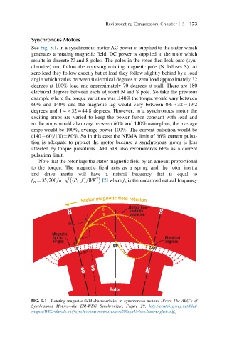
See Fig. 5.1. In a synchronous motor AC power is supplied to the stator which
generates a rotating magnetic field. DC power is supplied to the rotor which
results in discrete N and S poles. The poles in the rotor then lock onto (syn-
chronize) and follow the opposing rotating magnetic pole (N follows S). At
zero load they follow exactly but at load they follow slightly behind by a load
angle which varies between 0 electrical degrees at zero load approximately 32
degrees at 100% load and approximately 70 degrees at stall. There are 180
electrical degrees between each adjacent N and S pole. So take the previous
example where the torque variation was 40% the torque would vary between
60% and 140% and the magnetic lag would vary between 0.6 32¼19.2
degrees and 1.4 32¼44.8 degrees. However, in a synchronous motor the
exciting amps are varied to keep the power factor constant with load and
so the amps would also vary between 60% and 140% nameplate, the average
amps would be 100%, average power 100%. The current pulsation would be
(140 60)/100¼80%. So in this case the NEMA limit of 66% current pulsa-
tion is adequate to protect the motor because a synchronous motor is less
affected by torque pulsations. API 618 also recommends 66% as a current
pulsation limit.
Note that the rotor lags the stator magnetic field by an amount proportional
to the torque. The magnetic field acts as a spring and the rotor inertia
and drive inertia will have a natural frequency that is equal to
2
f ¼ 35;200=n √ P r fð Þ=WK [2] where f n is the undamped natural frequency
n
Stator magnetic field rotation
D
M
E
∞ ∞ ∞
∞
otor
FIG. 5.1 Rotating magnetic field characteristics in synchronous motors. (From The ABC’s of
Synchronous Motors—the EM-WEG Synchronizer, Figure 29, http://ecatalog.weg.net/files/
wegnet/WEG-the-abcs-of-synchronous-motors-usaem200syn42-brochure-english.pdf.)