
Page 269 - Compression Machinery for Oil and Gas
P. 269
254 SECTION II Types of Equipment
FIG. 6.1 Compression progression.
Positive displacement machines do not transfer a certain speed-related
amount of kinetic energy to the gas which is converted into pressure like cen-
trifugal compressors but compress the gas “quasi-statically.” The enthalpy dif-
ference per mass unit of gas transferred into the gas can vary heavily for
different gases. Therefore, the concept of head does not make sense for positive
displacement machines and the use of an h-s diagram is not helpful.
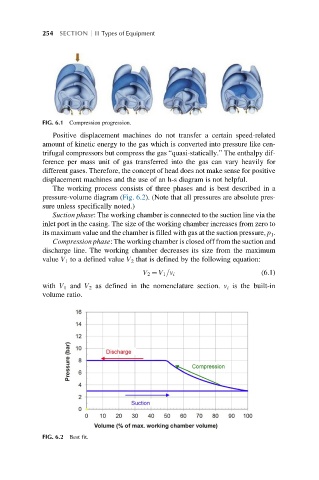
The working process consists of three phases and is best described in a
pressure-volume diagram (Fig. 6.2). (Note that all pressures are absolute pres-
sure unless specifically noted.)
Suction phase: The working chamber is connected to the suction line via the
inlet port in the casing. The size of the working chamber increases from zero to
its maximum value and the chamber is filled with gas at the suction pressure, p 1 .
Compression phase: The working chamber is closed off from the suction and
discharge line. The working chamber decreases its size from the maximum
value V 1 to a defined value V 2 that is defined by the following equation:
(6.1)
V 2 ¼ V 1 =v i
with V 1 and V 2 as defined in the nomenclature section. v i is the built-in
volume ratio.
FIG. 6.2 Best fit.