
Page 309 - Compression Machinery for Oil and Gas
P. 309
294 SECTION II Types of Equipment
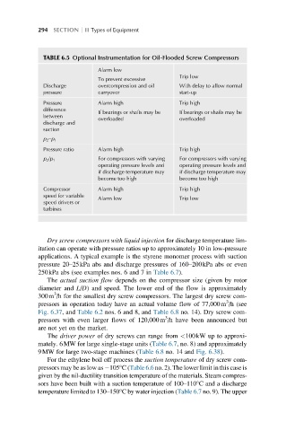
TABLE 6.5 Optional Instrumentation for Oil-Flooded Screw Compressors
Alarm low
Trip low
To prevent excessive
Discharge overcompression and oil With delay to allow normal
pressure carryover start-up
Pressure Alarm high Trip high
difference If bearings or shafts may be If bearings or shafts may be
between overloaded overloaded
discharge and
suction
p 2 –p 1
Pressure ratio Alarm high Trip high
p 2 /p 1 For compressors with varying For compressors with varying
operating pressure levels and operating pressure levels and
if discharge temperature may if discharge temperature may
become too high become too high
Compressor Alarm high Trip high
speed for variable Alarm low Trip low
speed drivers or
turbines
Dry screw compressors with liquid injection for discharge temperature lim-
itation can operate with pressure ratios up to approximately 10 in low-pressure
applications. A typical example is the styrene monomer process with suction
pressure 20–25kPa abs and discharge pressures of 160–200kPa abs or even
250kPa abs (see examples nos. 6 and 7 in Table 6.7).
The actual suction flow depends on the compressor size (given by rotor
diameter and L/D) and speed. The lower end of the flow is approximately
3
300m /h for the smallest dry screw compressors. The largest dry screw com-
3
pressors in operation today have an actual volume flow of 77,000m /h (see
Fig. 6.37, and Table 6.2 nos. 6 and 8, and Table 6.8 no. 14). Dry screw com-
3
pressors with even larger flows of 120,000m /h have been announced but
are not yet on the market.
The driver power of dry screws can range from <100kW up to approxi-
mately. 6MW for large single-stage units (Table 6.7, no. 8) and approximately
9MW for large two-stage machines (Table 6.8 no. 14 and Fig. 6.38).
For the ethylene boil off process the suction temperature of dry screw com-
pressors may be as low as 105°C(Table 6.6 no. 2). The lower limit in this case is
given by the nil-ductility transition temperature of the materials. Steam compres-
sors have been built with a suction temperature of 100–110°Cand adischarge
temperature limited to 130–150°C by water injection (Table 6.7 no. 9). The upper