
Page 316 - Compression Machinery for Oil and Gas
P. 316
Screw Compressors Chapter 6 301
temperatures are not a fixed limit but the manufacturing clearances at ambient
temperature must be much larger than usual to compensate for the thermal growth
and the design of the clearances gets difficult.
Screw compressors can operate with a large variation of molecular weights
as long as the discharge temperature is limited (see Table 6.6 no. 5 and Table 6.8
nos. 15 and 16).
Design Range for Oil-Flooded Screws
The maximum discharge pressure for oil-flooded screws is limited by the casing
design. Virtually all oil-flooded screw compressors feature a vertically (radi-
ally) split casing. Typical design pressures are in the range of 2.5–3MPa, with
some available up to 10MPa. As with oil-free screws, in many cases the com-
pressor may not be able to operate at the maximum discharge pressure of the
casing due to other limitations.
The same differentiation between maximum discharge pressure and maxi-
mum allowable differential pressure discussed for oil-free screws above also
applies to oil-flooded screws. However, with oil-flooded, it is much more fea-
sible for these two values to be the same. For example, it is possible to achieve a
pressure ratio of 25:1 in some cases.
Undercompression is generally not an issue with oil-flooded screws. This is
partly due to the damping effect of the oil on any pulsations in the system. And
since the injected oil carries away most of the heat of compression, it is usually
possible to avoid thermal limits by adjusting the quantity of oil injection.
The actual suction flow depends on the compressor size (given by rotor
diameter and L/D) and speed. The lower end of the flow is approximately
3
200m /h for the smallest oil-flooded screw compressors. The largest available
3
today have an actual volume flow of 30,000m /h.
The driver power of flooded screws can range from <100kW up to approx-
imately 9MW for large single-stage units. It should be noted that screw com-
pressor sizes are more often defined by flow than power; therefore, it is
uncommon (and technically incorrect) to refer to a screw compressor as, for
example, a “2mW compressor.”
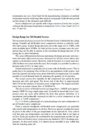
Fig. 6.38 shows a photograph of a typical package size and configuration of
an oil-flooded screw compressor.
From a material standpoint, oil-flooded screw compressors can generally
take similar inlet temperatures as oil-free. However, special consideration must
be given to the effect of the gas temperature on the injected oil. Very cold or
very hot inlet gas temperatures can lead to oil viscosity that is too high or
too low. Each case needs to be confirmed by the manufacturer and the oil sup-
plier. Most oil-flooded screw compressors are limited to 120°C discharge tem-
perature. As discussed earlier, it is almost always possible to stay within this
limit by injecting more oil.