
Page 74 - Compression Machinery for Oil and Gas
P. 74
Centrifugal Compressors Chapter 3 65
Rotordynamic Modeling and Analysis
Rotordynamic modeling begins by modeling the rotor with beam or three-
dimensional (3D) finite elements. The compressor rotor, or shaft, is modeled
as a series of smaller segments, or elements, that appropriately capture the
diameter steps and attachment points for all added mass components. A node
or station is the start or end of each element. Components like impellers, cou-
plings half-weights, DGSs, and thrust disks generally do not add shaft stiffness,
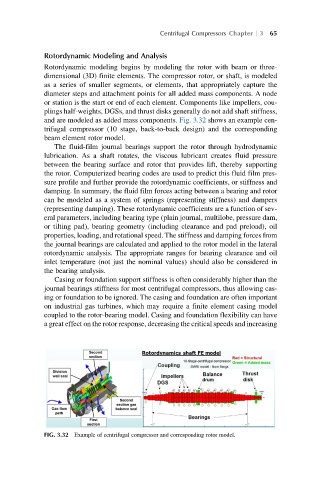
and are modeled as added mass components. Fig. 3.32 shows an example cen-
trifugal compressor (10 stage, back-to-back design) and the corresponding
beam element rotor model.
The fluid-film journal bearings support the rotor through hydrodynamic
lubrication. As a shaft rotates, the viscous lubricant creates fluid pressure
between the bearing surface and rotor that provides lift, thereby supporting
the rotor. Computerized bearing codes are used to predict this fluid film pres-
sure profile and further provide the rotordynamic coefficients, or stiffness and
damping. In summary, the fluid film forces acting between a bearing and rotor
can be modeled as a system of springs (representing stiffness) and dampers
(representing damping). These rotordynamic coefficients are a function of sev-
eral parameters, including bearing type (plain journal, multilobe, pressure dam,
or tilting pad), bearing geometry (including clearance and pad preload), oil
properties, loading, and rotational speed. The stiffness and damping forces from
the journal bearings are calculated and applied to the rotor model in the lateral
rotordynamic analysis. The appropriate ranges for bearing clearance and oil
inlet temperature (not just the nominal values) should also be considered in
the bearing analysis.
Casing or foundation support stiffness is often considerably higher than the
journal bearings stiffness for most centrifugal compressors, thus allowing cas-
ing or foundation to be ignored. The casing and foundation are often important
on industrial gas turbines, which may require a finite element casing model
coupled to the rotor-bearing model. Casing and foundation flexibility can have
a great effect on the rotor response, decreasing the critical speeds and increasing
FIG. 3.32 Example of centrifugal compressor and corresponding rotor model.