
Page 84 - Compression Machinery for Oil and Gas
P. 84
74 SECTION II Types of Equipment
is assessed by studying the respective mode shapes and potential excitation
mechanisms.
The SM for a mode can be calculated as follows:
SM ¼ |f e f n |=f e
such that SM is the SM, f e is the frequency of excitation, and f n is the natural
frequency of concern. SMs of more than 10% are preferred or a force response
analysis is required.
A forced response analysis is usually conducted to determine anticipated
stress levels in the shafting during normal loaded operation. For turbine drives,
whole mechanical excitation orders are usually considered. Trains involving
motors, slip, and/or VFD frequencies are normally evaluated in addition to
whole mechanical orders. During the forced response calculations, stress con-
centration factors are developed to account for keyways, major diameter
changes, fillet radii, etc. based on shaft geometry. The resultant intensified
stress at each station in the model is compared against allowable stress recom-
mendations to determine acceptability.
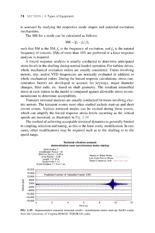
Transient torsional analyses are usually conducted for trains involving elec-
tric motors. The transient events most often studied include start-up and short
circuit events. Various torsional modes can be excited during these events,
which can amplify the forced response stress levels occurring as the critical
speeds are traversed, as illustrated in Fig. 3.39.
The method of achieving acceptable torsional dynamics is generally limited
to coupling selection and tuning, as this is the least costly modification. In rare
cases, other modifications may be required such as to the shafting or to the
speed range.
Torsional vibration analysis
demonstration case–synchronous motor startup
Shaft Section 7
Amplification Factor = 30
Effective Radius = 8.25 in
Maximum Shear Stress
Inner Radius = 0.00
Low Cycle Failure Stress
Length = 27.30 in
Shear Endurance Limit
Speed Ratio = 1.0
Shear Modulus = 1.18 e+7 pai
18,000
14,000
Predicted Number of Tolerable Events: 4361
10,000
Stress (psi) –2000
6000
2000
–6000
–10,000
–14,000
–18,000
0 2 4 6 8 10 12
Time (s)
FIG. 3.39 Representative transient torsional results—synchronous motor start-up (SwRI results
from the University of Virginia-ROMAC TORTRAN code).