
Page 214 - Construction Waterproofing Handbook
P. 214
ABOVE-GRADE WATERPROOFING 3.101
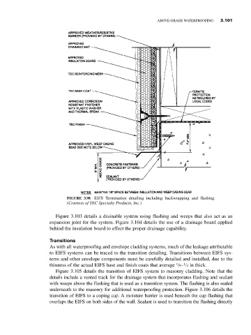
FIGURE 3.98 EIFS Termination detailing including backwrapping and flashing.
(Courtesy of TEC Specialty Products, Inc.)
Figure 3.103 details a drainable system using flashing and weeps that also act as an
expansion joint for the system. Figure 3.104 details the use of a drainage board applied
behind the insulation board to effect the proper drainage capability.
Transitions
As with all waterproofing and envelope cladding systems, much of the leakage attributable
to EIFS systems can be traced to the transition detailing. Transitions between EIFS sys-
tems and other envelope components must be carefully detailed and installed, due to the
1
1
thinness of the actual EIFS base and finish coats that average 8– 4 in thick.
Figure 3.105 details the transition of EIFS system to masonry cladding. Note that the
details include a vented track for the drainage system that incorporates flashing and sealant
with weeps above the flashing that is used as a transition system. The flashing is also sealed
underneath to the masonry for additional waterproofing protection. Figure 3.106 details the
transition of EIFS to a coping cap. A moisture barrier is used beneath the cap flashing that
overlaps the EIFS on both sides of the wall. Sealant is used to transition the flashing directly