
Page 22 - Construction Waterproofing Handbook
P. 22
1.4 CHAPTER ONE
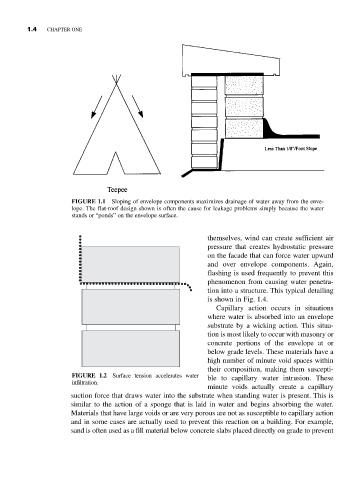
FIGURE 1.1 Sloping of envelope components maximizes drainage of water away from the enve-
lope. The flat-roof design shown is often the cause for leakage problems simply because the water
stands or “ponds” on the envelope surface.
themselves, wind can create sufficient air
pressure that creates hydrostatic pressure
on the facade that can force water upward
and over envelope components. Again,
flashing is used frequently to prevent this
phenomenon from causing water penetra-
tion into a structure. This typical detailing
is shown in Fig. 1.4.
Capillary action occurs in situations
where water is absorbed into an envelope
substrate by a wicking action. This situa-
tion is most likely to occur with masonry or
concrete portions of the envelope at or
below grade levels. These materials have a
high number of minute void spaces within
their composition, making them suscepti-
FIGURE 1.2 Surface tension accelerates water ble to capillary water intrusion. These
infiltration.
minute voids actually create a capillary
suction force that draws water into the substrate when standing water is present. This is
similar to the action of a sponge that is laid in water and begins absorbing the water.
Materials that have large voids or are very porous are not as susceptible to capillary action
and in some cases are actually used to prevent this reaction on a building. For example,
sand is often used as a fill material below concrete slabs placed directly on grade to prevent