
Page 51 - Design of Reinforced Masonry Structures
P. 51
2.4 CHAPTER TWO
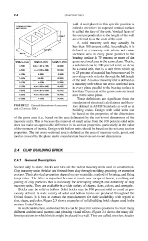
wall. A unit placed in this specific position is
called a stretcher; its exposed vertical surface
is called the face of the unit. Vertical faces of
the unit perpendicular to the length of the wall
are referred to as the ends of the unit.
A solid masonry unit may actually be
less than 100 percent solid. Accordingly, it is
defined as a masonry unit whose net cross-
sectional area in every plane parallel to the
bearing surface is 75 percent or more of the
gross-sectional area in the same plane. That is,
a solid unit can be 100 percent solid, or it can
be a cored unit, that is, a unit from which up
to 25 percent of material has been removed by
providing voids or holes through the full height
of the unit. A hollow masonry unit is defined as
a masonry unit whose net cross-sectional area
in every plane parallel to the bearing surface is
less than 75 percent of the gross cross-sectional
area in the same plane.
These definitions are significant from the
standpoint of structural calculations and there-
FIGURE 2.2 General dimensions of a masonry fore defined in ASTM Standards as well as in
unit. (Courtesy: BIA.)
building codes. Design with solid units can
be based on the properties of the dimensions
of the gross area (i.e., based on the area delineated by the out-to-out dimensions of the
masonry unit). This is because the removal of small areas from the 100 percent solid units
does not make an appreciable difference in its section properties, particularly in the value
of the moment of inertia. Design with hollow units should be based on the net area section
properties. The net cross-sectional area is defined as the area of masonry units, grout, and
mortar crossed by the plane under consideration based on out-to-out dimensions.
2.4 CLAY BUILDING BRICK
2.4.1 General Description
Second only to stone, bricks and tiles are the oldest masonry units used in construction.
Clay masonry units (bricks) are formed from clay through molding, pressing, or extrusion
process. Their physical properties depend on raw materials, method of forming, and firing
temperature. The latter is important because it must cause incipient fusion, a melting and
joining of clay particles that is necessary for developing strength and durability of clay
masonry units. They are available in a wide variety of shapes, sizes, colors, and strengths.
Bricks may be solid or hollow. Solid bricks may be 100 percent solid or cored as pre-
viously defined. A wide variety of solid and hollow bricks are produced throughout the
United States. It is best to contact the manufacturers for their availability with regard to
size, shape, and color. Figure 2.3 shows examples of solid building brick shapes used in the
western United States.
In wall construction, individual bricks can be placed in various positions to create many
different architectural patterns and pleasing visual effects. Figure 2.4 shows the many dif-
ferent positions in which bricks might be placed in a wall. They are called stretcher, header,