
Page 133 - Design of Solar Thermal Power Plants
P. 133
120 3. GENERAL DESIGN OF A SOLAR THERMAL POWER PLANT
directed to the effective solar cone around the incident sun beam direction
after reflection. All optical errors are convoluted into the effective solar
cone. The brightness distribution of the effective solar cone is here
assumed to be circular and Gaussian. The mirror curvature can be
adequately formulated using a certain number of local normal vectors at
the mirror cell centers of the heliostat.
The principle of the BRT method coupled with the effective sun-shape
(solar cone brightness distribution) is schematically illustrated by Fig. 3.1.
.
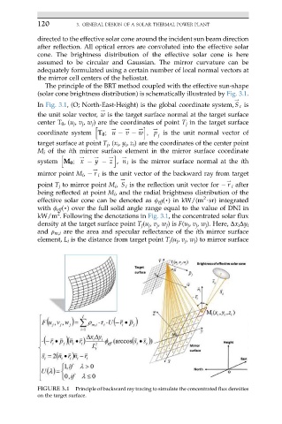
In Fig. 3.1, (O; North-East-Height) is the global coordinate system, S c is
.
the unit solar vector, w is the target surface normal at the target surface
center T 0 ,(u j , v j , w j ) are the coordinates of point T j in the target surface
. . . .
h i
coordinate system T 0 ; u v w ; p is the unit normal vector of
j
target surface at point T j ,(x i , y i , z i ) are the coordinates of the center point
M i of the ith mirror surface element in the mirror surface coordinate
h . . . i .
system M 0 ; x y z , n i is the mirror surface normal at the ith
.
mirror point M i , r i is the unit vector of the backward ray from target
. .
point T j to mirror point M i , S i is the reflection unit vector for r i after
being reflected at point M i , and the radial brightness distribution of the
2
effective solar cone can be denoted as f eff (,) in kW/(m $sr) integrated
with f eff (,) over the full solid angle range equal to the value of DNI in
2
kW/m . Following the denotations in Fig. 3.1, the concentrated solar flux
density at the target surface point T j (u j , v j , w j )is F(u j , v j , w j ). Here, Dx i Dy i
and r m,i are the area and specular reflectance of the ith mirror surface
element, L i is the distance from target point T j (u j , v j , w j ) to mirror surface
FIGURE 3.1 Principle of backward ray tracing to simulate the concentrated flux densities
on the target surface.