
Page 32 - Design of Solar Thermal Power Plants
P. 32
1.2 BRIEF INTRODUCTION TO SOLAR THERMAL POWER GENERATION 25
TABLE 1.3 Parameters for Parabolic Trough Solar Power Collector
Item Parameters Item Parameters
Total area/m 2 9000 Glazed shield tube wall 3
thickness/mm
Aperture area/m 2 9000 Single-piece receiver tube 4060
length/mm
Aperture width/m 5.76 Total length of receiver 97,440
tube/mm
Focal length/mm 1.71 Total length of collector/m 1500
Glass thickness of 4 Tracking precision/( ) 0.1
mirror/mm
Thickness of glass 3.2 Maximum operating 400
mirror/mm temperature/ C
Exterior diameter of 70 Maximum operating 1.6
metalreceivertube/mm pressure/MPa
Exterior diameter of 120 Tracking axis direction 3000 m 2
glazed shield tube/mm northesouth
6000 m 2
westeeast
Provided by the Institute of Electrical Engineering, Chinese Academy of Sciences, 2017.
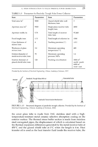
FIGURE 1.13 Structural diagram of parabolic trough collector. Provided by the Institute of
Electrical Engineering, Chinese Academy of Sciences, 2010.
the cover glass tube is made from 316L stainless steel with a high-
temperature-resistant metal ceramic selective absorption coating on the
exterior surface. The thermal stress buffer section is made from stainless
steel corrugated pipes, the displacement of which is calculated based on
the thermal expansion differences generated by the metal receiver tube at
450 C and the glazed shield tube at 0 C when the length is 4 m. Heat
transfer oil is used as the heat transfer fluid inside the receiver tube, the