
Page 229 - Distillation theory
P. 229
P1: FCH/FFX P2: FCH/FFX QC: FCH/FFX T1: FCH
0521820928c06 CB644-Petlyuk-v1 June 11, 2004 20:17
6.8 Calculation of Minimum Reflux Mode for Distillation Complexes 203
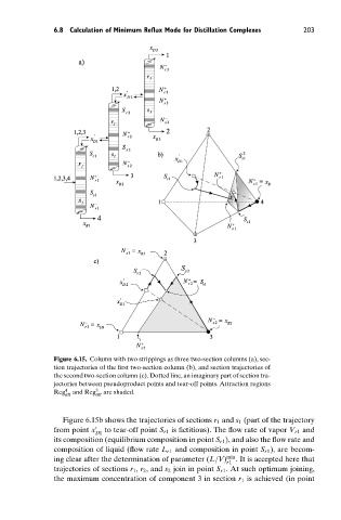
Figure 6.15. Column with two strippings as three two-section columns (a), sec-
tion trajectories of the first two-section column (b), and section trajectories of
the second two-section column (c). Dotted line, an imaginary part of section tra-
jectories between pseudoproduct points and tear-off points. Attraction regions
Reg 4 att and Reg 3 att are shaded.
Figure 6.15b shows the trajectories of sections r 1 and s 1 (part of the trajectory
from point x to tear-off point S r1 is fictitious). The flow rate of vapor V r1 and
D1
its composition (equilibrium composition in point S r1 ), and also the flow rate and
composition of liquid (flow rate L r1 and composition in point S r1 ), are becom-
ing clear after the determination of parameter (L/V) min . It is accepted here that
r1
trajectories of sections r 1 , r 2 , and s 2 join in point S r1 . At such optimum joining,
the maximum concentration of component 3 in section r 1 is achieved (in point