Page 250 - Distillation theory
P. 250

P1: JPJ/FFX  P2: JMT/FFX  QC: FCH/FFX  T1: FCH
            0521820928c07  CB644-Petlyuk-v1                                                      June 11, 2004  20:18


                        224    Trajectories of the Finite Columns and Their Design Calculation

                                     2
                                          +
                               (x F − S − N ) lin . The equation of this straight line can be found by means of solv-
                                     s    s
                               ing the system of equations describing the mentioned manifolds by coordinates
                               of the stationary points entering into them and of point x F . Then the coordinates
                                                    ∞ sh
                               of points (x min sh  and (x )  at this straight line are determined from Eq. (5.18).
                                           )
                                         f −1 lin   f  lin
                                                          )
                               The coordinates of points (x min sh  and (x ∞  ) sh  are determined in the same way
                                                        f  lin     f −1 lin
                               (Fig. 7.1c).
                                 Possible composition segments at the first trays above and below the feed cross-
                               section in the real columns [x f −1 ] and [x f ] located at vicinity of curvilinear sepa-
                                                          2
                                                                                  2
                                                                             1
                                                     1
                                                                                       +
                               ratrix manifolds Reg sh,R (S − S − N ) and Reg sh,R (S − S − N ), or inside the
                                                               +
                                                sep,r  r  r    r        sep,s  s  s   s
                               working trajectory bundles Reg R  and Reg R  , correspond to segments [x f −1 ] sh
                                                          w,r        w,s                          lin
                               and [x f ] sh  .
                                      lin
                                                   1
                                                               2
                                                                    +
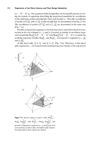
                                 At the direct split, S ≡ N and S ≡ N (Fig. 7.2a). Therefore, at the direct
                                                        −
                                                   r    r      s    s
                               split, segment [x f −1 ] is located inside working trajectory bundle of the top section
                                    x               2
                                     D
                               x F    a)
                                    x
                                     B
                                           x ∞
                                        min  f−1
                                       x
                                        f−1
                                        x D
                                                    min
                                                   x
                                         1          f              4
                                        ∞
                                       x ≡ N +
                                        f  s
                                                3
                                                    2
                                      b)
                                                       x  min
                                                        f−1
                                                    ∞             ∞   +
                                                   x             x  ≡ N
                                                    f             f−1  r
                                                                  x min
                                                                   f
                                         1                         4
                                                                x
                                                                 B
                                                3
                                                                 2,3,4
                               Figure 7.2. Section regions at given reflux Reg R w,r  =
                                       1         1,2,3         4  1
                                                          4
                                  1
                               Reg , Reg sh,R  and Reg  R  = Reg , Reg sh,R  and
                                  att  sep,s      w,s     att  sep,r
                                      2,3,4       4           1,2,3
                               possible composition segments [x f −1 ] and [x f ] in feed
                               cross-section: (a) direct split, (b) indirect split. Separa-
                               trix sharp split section regions are shaded.
   245   246   247   248   249   250   251   252   253   254   255