Page 72 - Distillation theory
P. 72

P1: JPJ/FFX  P2: FCH/FFX  QC: VINOD/IYP  T1: FCH
            0521820928c03  CB644-Petlyuk-v1                                                      June 11, 2004  20:12


                        46     Trajectories of Distillation in Infinite Columns Under Infinite Reflux

                                           2                             2
                               a)                              b)


                                         2
                                            4
                                1        3                                    x B
                                              x B  8
                                   x D
                                          x F                          x F
                                       7
                                1                  1     4   1                        4
                                             5
                                                              x D
                                                       6
                                           3                             3

                                           2                              2
                                 c)                             d)


                                   x D

                                                                x D
                                                                               x B
                                         x F                            x F
                               1                        4     1                        4

                                                  x B

                                           3                              3
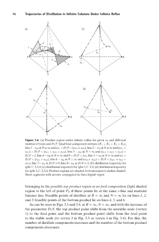
                               Figure 3.4. (a) Product region under infinite reflux for given x F and different
                               number of trays and D/F. Ideal four-component mixture (K 1 > K 2 > K 3 > K 4 ),
                               line1−x D atN=∞andx F1 <D/F<(x F1 +x F2 ),line2−x D atN=∞and(x F1 +
                               x F2 ) < D/F < (x F1 + x F2 + x F3 ), line 3 − x D at N =∞ and (x F1 + x F2 + x F3 ) <
                               D/F < 1, line 4 − x B at N =∞ and 0 < D/F < x F1 , line 5 − x B at N =∞ and x F1 <
                               D/F < (x F1 + x F2 ), line 6 − x B at N =∞ and (x F1 + x F2 ) < D/F < (x F1 + x F2 +
                               x F3 ), line 7− x D at D/F = 0, line 8− x B at D/F = 1; (b) distillation trajectory for
                               split 1 : 2,3,4; (c) distillation trajectory for split 1,2 : 3,4; (d) distillation trajectory
                               for split 1,2 : 2,3,4. Product regions are shaded, bottom region is darker shaded.
                               Short segments with arrows, conjugated tie-lines liquid–vapor.


                               belonging to the possible top product region at set feed composition (light shaded
                               region to the left of point F), if these points lie at the same c-line and material
                               balance line. Feasible points of distillate at R =∞ and N =∞ lie on lines 1, 2,
                               and 3; feasible points of the bottom product lie on lines 4, 5, and 6.
                                 As can be seen in Figs. 3.3 and 3.4, at R =∞, N =∞, and with the increase of
                               the parameter D/F, the top product point shifts from the unstable node (vertex
                               1) to the feed point and the bottom product point shifts from the feed point
                               to the stable node (to vertex 3 in Fig. 3.3 or vertex 4 in Fig. 3.4). For this, the
                               number of distillate components increases and the number of the bottom product
                               components decreases.
   67   68   69   70   71   72   73   74   75   76   77